Sunday, March 25, 2018

Cities with Cars!

I showed off procedural cities with road networks in a previous post. I'm continuing to add features to my procedural city in 3DWorld. This time I've been working on adding moving cars. Initially, I just wanted to add simple cars that drove around the roads as a type of detail object to bring the city to life. But I kept adding more and more to the car system, and it got pretty interesting. Not only did I add cars, but I added traffic lights as well.

I've added various config file parameters for cars to control their number, size, speed, etc. I'm currently generating between 1000 and 10,000 cars of various colors and placing them within the roads on the seven cities of this map. Cars move around within a city, make turns, and travel between cities. The car AI update logic is very fast, consuming only 1.8ms for 10,000 cars. This is because cars only update their state every so often, rather than every frame. The majority of cars tend to be either traveling at a constant speed on a straight road, stopped at a traffic light, or stopped behind another car. In all of these cases, no velocity or direction update is needed, and the cars don't need to determine which direction to turn. These decisions are triggered by infrequent change-of-state events such as when a car's origin crosses into a new intersection or road segment, when the traffic light turns green, or when the car in front starts moving.

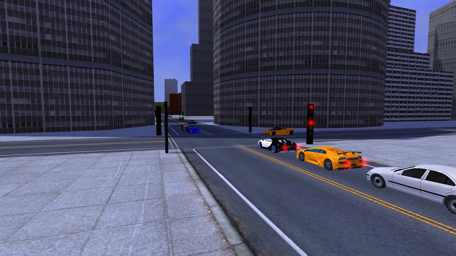
I added traffic lights at all 3-way and 4-way intersections to help control the cars and make the streets look more interesting. I used a minimalist, modern traffic light design. The lights for each direction are in a single vertical cube, with straight and right turn lights on the bottom section and left turn lights (if present) on the top. Red, yellow, and green lights are ordered from top to bottom to match standard traffic light arrangements. I made the light housing black so that I didn't have to worry about shadows and normals (for now). I created the turn arrows in Gimpshop. Lit lights also have an emissive overlay glow texture with additive blending to make them appear brighter, especially at night.

Traffic lights use a finite state machine with states that include a subset of {east left turn, east and west straight + right turn, west left turn, north left turn, north and south straight + right turn, south left turn}, in this order. Some intersections don't have left turns, so their number of states is smaller. The left turn signals have a shorter duration, and cars can sometimes make rights on red. There are currently no U-turns. I'm not sure why that would be needed other than in cases of navigational error, which doesn't happen here.

I started off drawing cars as simple colored, untextured cubes. Then I made them two cubes, one for the bottom and another for the top. I added brake lights for when cars are slowing or stopping, headlights at night, and turn signals that flash on and off when the cars are about to turn. My initial work, using these placeholder car models, is shown in the screenshot below. This is an initial prototype I used to get the vehicle motion right, and has been improved since that screenshot was taken.

Cars were initially drawn as two untextured rectangles, and distant cars are still drawn this way. At least the traffic lights look reasonable.

I tried to model vehicle physics as accurately as possible, including realistic acceleration, deceleration (braking), and turn radius. Deceleration is much higher than acceleration, which means cars can stop quickly at red lights but take a while to accelerate to max speed. Cars move faster when going downhill and slower going uphill. Some cars have higher max speed than others. These tend to form lines/groups of cars where the faster ones are following the slower ones.

Each car is driven by an AI that decides which way to turn at each intersection. I could probably use real path planning here by choosing a destination for each car and calculating the fastest route to get there. This would require writing an algorithm similar to what's used in a GPS. Of course, when there are many cars, the user can't actually tell the difference between random turns and route planning. I suppose this requires picking one car and following it around the city. Furthermore, it's difficult for me to even test path finding in this situation. Turns aren't entirely random; some of the faster cars will turn to go around a slow car that's in front of them.

Cars follow traffic lights, and they slow down for yellow lights and to avoid rear-ending other cars. Each car stays in the proper lane and makes legal turns. I added safe right turns on red when no other cars are traveling in that lane. I implemented collision detection, though the AI is pretty good about not colliding with other cars as long as traffic lights are obeyed. Cars always stay on the roads, so I don't need to worry about collisions with traffic lights or buildings. Collisions between two cars do occasionally happen, usually because a car can't stop fast enough or other cars are blocking the intersection. I found out the hard way that cars starting to pull out into the intersection can collide with cars that entered the intersection in another direction just before the light turned red. That's why yellow lights are needed!

It's been infuriatingly difficult to keep the cars from colliding or getting stuck in all cases. Everything runs pretty smoothly in most cases, but when I add too many cars, things start to break down. One of the problems is that traffic can back up and cars will stop behind other cars in the middle of an intersection. Maybe they should stop early to avoid blocking cross traffic, if I could find some way to efficiently implement that. However, I think it's reasonable to allow them to stop in the intersection. After all, that happens with real drivers. I take Uber home from work each day. We often make a left turn at a big intersection outside my office. If I don't leave late enough, traffic is backed up and cars are often stopped in the intersection, blocking our way.

I changed the car logic to make cars wait at the light if the intersection is blocked in front of them, even if the light is green. This fixes the problem in most cases, but can result in gridlock when the density of cars in one area is too high. There are situations where two long lines of cars going in opposite directions end in a car trying to make a left turn. The turn is blocked by the line of cars in the other direction, so all the cars just sit there. I think adding a left turn lane would help, though that requires using a set of road textures that has two lanes in each direction. I suppose this is why so many real roads have left turn lanes.

This fix doesn't quite work in all cases. If the intersection is clear, and cars start to pull out, they can become backed up at the next traffic light. One car may be stopped mid-turn, while the car behind it has already started to pull out into the intersection.  The car behind will collide with the car in front if the front car has crossed the halfway point and is considered to now be on the other (new) road. If I make the back car wait, the light can change to red while it's waiting, and cars coming from the other direction can collide with its front end. It's technically not completely in the intersection, and the intersection hasn't yet been flagged as blocked. The real solution seems to require some amount of planning ahead and anticipating problems, which is easy for people but difficult (and slow) for computers. Now I know how self driving cars must feel.

Another problem is that traffic tends to build up at the intersections on the connector roads between cities. Cars are biased toward taking these roads, even though these roads are still single lane. They can get pretty packed with cars. They do have twice the speed limit, but this only allows the cars to pile up faster. Again, the problem is mostly due to that one car waiting to make a left turn at the intersection that leads into the city. It would probably help if the connector road intersection was 4-way rather than a 3-way T junction. I adjusted the traffic light pattern to assign longer times to the incoming direction of that intersection. This helps with the backup at connector road intersections, while making the gridlock worse for cars trying to cross through that intersection from within the city. Oh well, it's good enough for now.

I'm sure you're all thinking about how bad those cube cars look. I was thinking the same thing! Yes, I need better 3D models. I don't have any 3D modeling tools, and I wouldn't know how to use them anyway, so it's off to Google to find some free 3D car models. My first attempt at using 3D models for cars didn't turn out as I expected. Some (most?) 3D modeling tools have the ground as the XZ plane and Y as up. 3DWorld uses XY for the ground and Z for up. I found this easier because I could use 2D math library classes that operated in XY for the terrain, then extend them upward by adding a Z component. I guess I need to add a 90 degree rotation to fix this. The screenshot below is too silly for me to leave out.

First attempt at adding real 3D models for cars. Something's not quite right about these cars. Hmm.

Also note that the cars are different sizes. This seemed fine with cube cars, but looks odd when they're all the same complex 3D model. I've made them all the same size in the remaining screenshots.

This first sports car model is pretty good quality. I downloaded the model in .obj format from the McGuire Computer Graphics Archive. It's way higher detail than I need though, especially considering it has a full interior and engine that can't even be seen from the outside. That's fine, I was able to use the same level of detail (LOD) trick I used with the 10,000 museum objects. 10K cars, 10K museums, it's all the same. See, I knew I could find a real use for that model LOD/instancing system. The one problem with this model is that some of the triangles on the top rear of the car have bad normals that face inward instead of outward, making them appear too dark in the sun. I assume it's a problem with the triangle vertex winding order (CW vs. CCW) in the .obj file. It's not something I can easily fix, so I'll have to live with it. You may notice this in some of the images below.

These models aren't perfect. The wheels don't actually rotate while the car is moving, and don't turn when the car is turning. This makes cars appear a bit odd when they turn. Also, the transition from 3D models to a pair of cubes is noticeable in distant cars. This problem also isn't easy to fix, unless I'm willing to reduce the number of cars to something like 1000.

Speaking of images, here's a night scene where the sports cars have been colored and placed in the correct orientation. I disabled the buildings so that the distant headlights are easier to see.

Multi-colored sports cars in the city at night. Buildings have been disabled to make the headlights easier to see.

These look much better than the cube cars, even with the dark triangles. Headlights are on because it's night time. The glow of the bright lights has a nice effect. I wish I could add spotlights on the road, but I haven't figured out how to do this yet. It's difficult to add support for thousands of moving spotlights in a scene with this large a draw distance in a forward rendering engine. Here's another screenshot, this time during the day, and with buildings enabled.

City scene with sports cars on the roads during daytime.

I think we need more variety of cars. Back off to Google to find more 3D models... Okay, this looks better. Let's see, there are now six models: a police car, a white sedan, and three more exotic sports cars. I guess this is a city full of rich kids, and the police are needed to keep them under control. This is the set of six models out of the initial ~15 that passed the first quality filter. Some of these cars have minor problems with textures or normals, but are otherwise okay. And yes, if you look closely, the blue sports cars do have "Hot Wheels" painted on their hoods.

The cars come in various sizes and aspect ratios. I'm scaling them down to the same average size, but preserving the aspect ratio of the models. I use the same headlight, brake light, and turn signal locations for all models, based on the edges of the model's bounding cube. It makes drawing simpler, but the lights are sometimes outside of the car's bounds (especially for cars with curved front/read ends), or too high/low. I'll add several more screenshots below.

Police car making a left turn, viewed from above.


Various screenshots of cars driving on city roads and traversing intersections. There's still a lot of empty space between buildings that needs to be filled.

If you look carefully, distant cars are still drawn using cubes. I don't find this too distracting; at least they're colored to match the car models. Note that there are no car shadows, though traffic lights do have shadows. Cars can receive shadows, but don't cast shadows. This is difficult to do in an efficient way, considering the large number of dynamic models. If they were simple cubes like before, I could add their shadows pretty easily. Unfortunately, cube shadows look horrible with curved 3D models, and it's just too expensive to draw the entire 3D model of every car every frame for every shadow map. So for now I've left the shadows out. Maybe I can go back later and at least add simple dark areas under the cars due to ambient occlusion.

I really need to fill that empty space between buildings and roads with something. What can go here? Maybe parking lots? I could probably put some parked cars there, if I could find a good way to connect those areas to the roads.

Here is a different view showing cars on a long connector road, with a city in the background. The models are drawn tilted to match the slope of the road.

Cars driving on a long connector road between two cities, with a city in the distance.

This is another night time image, showing off car headlights and the glow of traffic lights in the dark. I hope the image isn't too dark to see. The sun and moon are both down so that the only lights are the faint ambient illumination, the car lights, and the traffic lights.

Cars of various types in a city at night. Hopefully this image isn't too dark.

Here I've increased the number of cars from 4,000 to 10,000 and removed the buildings to improve visibility. There are a ton of car models drawn, but they use LOD and this allows me to still get around 60 FPS. This also creates a lot of traffic congestion and related problems. This is probably too many cars to have in the current scene.

This is what you get when increasing the number of cars from 4,000 to 10,000. Buildings have been disabled again. I still get around 60 FPS in this case.

I recorded a video of cars in action, stopping at traffic lights and making smooth turns. You can see that everything works just as it does in the real world. Note that the video is sped up by 2x to make it shorter.


There are a lot of future work items for this post:
  • Add support for other vehicles such as trucks, buses, motorcycles, etc. (which requires finding new 3D models)
  • Fix the remaining problems with car collisions and traffic gridlock by improving the AI.
  • Add car shadows, or at least ambient occlusion.
  • Add spotlights for car headlights and make them shine on the roads, buildings, and other cars.
  • Add more city decorations: street signs, streetlights, benches, parking lots, bridges, etc.
  • Add parked cars as scenery.
  • Figure out how to make the car wheels actually turn.
  • Add support for multi-lane roads, and use a dedicated left turn lane to improve traffic.
I'm not sure how much of this I'll actually do, if any. This system works better than I had originally planned, given the amount of time and effort I spent on it. There are so many possible things I could be working on, considering the broader problem of populating the terrain with interesting content.

Bonus Update: I added ambient occlusion under cars using a single black quad and an opacity map texture with radial falloff.

Cars with ambient occlusion producing dark areas underneath.


Monday, February 26, 2018

Epic Fails in City Road Generation

This is a follow-up to my previous post on city generation where I show some of the fun bugs I had in the code and other failed attempts at placing roads. This first set shows off some actual bugs, though I had to go back and re-break the code in order to take these screenshots. Keep in mind that I did, in fact, encounter these problems when coding this stuff up. Roads aren't easy!

Here we have a road connecting two cities that are on opposite sides of this city shown in the screenshot. It was some problem with the tracking of which city the road is supposed to connect to. Roads are placed after city plots, so they have final say in what the terrain height should be.

But sir, you told me you wanted an express lane THROUGH the city!

This one was a failed intersection test between two connector roads. I was checking for overlap in all three dimensions (x, y, z). These roads don't overlap in z, but there's still an intersection. Just because they don't overlap in z doesn't mean they're okay! Only dimensions x and y should be checked. I had to print all sorts of debug text to the terminal to figure this one out. Doh!

We ran over budget constructing all these elevated roadways, and we didn't have the funds to dig the tunnel. We'll just have to put it on CA Proposition 39 in June for voter approval of a $9 parcel tax.

This is some problem with setting the height of the small 90-degree bend section at the wrong place in the control flow. The two 90-degree straight segments cause some interference here, and the bend has to smooth it over in a postprocessing pass. It took a while to come up with a fix for this one. I had to make several attempts before I got something that fixed all variants of this problem.

If you're not going to add a guard rail, can you at least post a warning sign? On second though, this might be good for drift racing!

Here's what happens when the slope direction Boolean is inverted. A number of different variables are XOR-ed together here to determine the sign of the slope of each road segment. It took a lot of trial-and-error to come up with the right conditionals. Maybe I shouldn't have been so greedy, trying to pack this info into a single byte in memory for each road segment. Ah well, I got it working in the end.

"Speed Bumps"

In this case, the two roads don't overlap, but their sloped boundaries do. The road on the right is created first. The road on the left is going to a higher altitude destination city. It creates a sharp cliff that falls to the right, then the smoothing pass smooths it out - right on top of the other road. The fix is to expand the road by its smoothing border before checking for intersections with other roads. It's a good change anyway, as it spaces roads out better. Bonus: the texture is all squished in that road segment in the lower left corner between the two intersections.

I'll take the high road and you take the low road. Sucker.

A similar problem can occur with cities, since they also have smoothing borders. I had to fix the problem in the same way as roads, by padding city bounding cubes by the smoothing distance prior to checking for intersections.

Someone forgot to build a retaining wall. Oops. I guess the 5th floor tenants get their backyard gardens after all.

I'm not sure exactly what caused steep roads to dip under the terrain. It's probably a floating-point rounding issue when converting to/from integer grid points/texels, or maybe during the 16-bit height <=> floating-point value calculation. One fix is to shift the road up in Z by an amount equal to (dz/dx)*pixel_size_in_x. I'm not sure if this is the correct solution as it causes steep roads to "float" above the terrain, but it's one of the only things I tried that works. As long as the steepness of the road is limited, it's not too noticeable.

Landslide!

At one point early in road development, I had a problem where the grass and roads were using two different coordinate systems. Grass is owned by the terrain tiles and is in tile-relative coordinates, which change as the player moves. Roads, cities, and buildings are always in constant global coordinates so that their vertex data can be stored on the GPU once and reused. A bit of math was required to fix this problem.

Can someone send a landscaping crew out to cut the grass growing on I-101? Maybe that will keep the cows from grazing in the middle of the road.

These next four screenshots weren't actual problems I ran into, but they still look interesting. This is the insanity resulting from disabling the connector road intersection tests so that they can go anywhere they want without restrictions.

Connecting every city directly to every other city is now possible, but not a good idea:

Ready for some off-road action? I think the engineer was off his meds when designing this.

A road was routed underneath this city. Presumably, it connects together two lower elevation cities on opposite sides of this one. I can't really tell in all the chaos. Some buildings have decided that they want to use the mesh height from the road rather than the mesh height for the rest of the city.

To protect against nuclear attacks, this shopping mall was built under the city. Or maybe it's a secret spy lair (with a big road leading up to it)?

This is the same problem, but inverted. Here the road connects together two higher elevation cities, dragging some buildings up with it. I could fix both of these issues by using the city elevation for buildings rather than terrain elevation. But this is just an experiment; this situation shouldn't come up, so why bother trying to handle it?

Now guests on every floor can have a room with a view! I just hope the kids don't decide to roll tires down that hill.

In this next case, the upper road was created first, and the lower roads were created later. Once a road is routed, it's done. The lower roads will modify the height of the terrain, but not the height of the upper road. In this particular case, it looks like a pretty cool bridge, though it needs some actual structure to be more realistic. Maybe I'll try to come up with a way to make this work. We still need to get rid of that road in the very front though.

A marvel of modern engineering, or a waste of our tax dollars?

That's all. I'll spare you the dozen or so screenshots of misaligned and incorrectly oriented road textures, which was another big time sink.

Sunday, February 25, 2018

Cities With Roads

It's been over a month since my last post. I had been working on fixing the ship AI for universe mode planet colonization, which required me to constantly run simulations on my PC. That topic doesn't make for a very interesting blog post because it's too technical and there aren't any good screenshots. However, in the past two weeks I've switched back to working on terrain and cities. This time I'm trying to combine the work I did with city generation and eroded terrain to create an environment that's a mix of natural and man-made structures. The end goal of the 3DWorld project is to generate a procedural universe that the player can seamlessly explore, from galaxies all the way down to individual trees and buildings. There's still so much work to do. The new addition to 3DWorld is city road networks.

I'm starting with the same 7Kx7K heightmap output from the erosion process described in a previous post. I exported it to a 65MB, 16-bit PNG image so that I can reload it without redoing the erosion simulation. This scene is huge, around 14km on a side. The cities are currently all placed in the relatively flat area in the bottom center of the map, between the ocean to the south and the mountain range to the north. Remember that this is an island, even though there's very little water in the screenshots below.

The steps I'm using to generate and connect cities are:
  1. Determine city location(s) by looking for relatively flat areas of the terrain, away from water
  2. Flatten a rectangular area of terrain to the city elevation (avg terrain elevation)
  3. Select the location of X and Y roads based on user-specified parameters
  4. Split roads into road segments, 2/3/4 way intersections, and building plots in between
  5. Create road networks that connect all cities (straight roads and roads with one 90-deg bend)
  6. Smooth the mesh around roads and intersections so that they're slightly above the terrain
  7. Generate procedural buildings and place them into the city plots
Items 1-6 are described here. Procedural building generation was explained in some previous blog posts and won't be discussed again. Look here and here for reference. All of these steps take less than one second of runtime: heightmap texture <=> floating-point array (330ms on 4 cores/8 threads), road network generation (70ms), and building generation/placement (185ms). This is much faster than the 2.1s actually spent loading the heightmap image as a texture.

City generation first reads a configuration file that specifies the size and number of cities, road length/width/spacing, max slope, terrain smoothing parameters, building parameters, etc. In total, there are 12 city parameters and 45 building generation parameters. These can all be edited by the user to customize city generation.

The first procedural generation step is selecting a site for each city. A few thousand locations are randomly chosen from the user-selected region of the heightmap, and the best one is selected. Locations are scored based on the RMS height difference between the average height and each height value around the perimeter of the city. I chose to use the perimeter rather than the full site area because it's more efficient to compute. Its unlikely for the player to notice if the city happens to flatten an entire hill or fill an entire valley anyway. It's more noticeable when there are steep slopes at the edges of the city. Each site must also not overlap a previous city, and must contain no water. I could have it fill in the water with land, but I do like to keep all of those small rivers and lakes.

Once the best site has been selected, that area is flattened to an elevation equal to the average elevation around the city perimeter. Note that the heightmap is normally stored as 16-bit integer values, but is converted to/from a floating-point array for the purposes of city generation. This conversion process takes about half the total city generation time. A boundary region is used to gradually transition from the city's elevation to the original terrain elevation to avoid sharp cliffs at the edge of the city. A smoothstep function is used to prevent slope discontinuities that would otherwise be obvious and appear unnatural to the player. Roads are flattened and smoothed in a similar way, but with a more complex function that handles fixed (but nonzero) slopes. The flattening step also replaces any grass inside the city perimeter with dirt.

Roads are placed on a uniform grid that exactly fills the city area, and are oriented in both the X (east-west) and Y (north-south) directions. The config file defines road width and spacing values. 4-way intersections are created in the interior of the city, 3-way intersections along the edges, and 2-way intersections at the corners. The space between roads is filled with a tiled concrete sidewalk texture that matches the border of the road and intersection textures. Buildings will be placed in these areas in the final step.

Intersections, plots, and road segments between intersections are sorted into the terrain tiles that contain their center points for drawing. This also serves as a useful spatial subdivision for later collision queries. For each visible tile, the city objects associated with it are drawn using the tile's shadow maps. This system is meant to scale to very large maps with potentially hundreds of cities, where only a subset of the cities is visible at any one time. I've tested it with 49K buildings and 90K road segments and still get 136 FPS (frames per second).

The screenshot below shows a pair of adjacent procedurally generated cities with roads and buildings. Note that the buildings all cast correct shadows on the roads and sidewalks. At this point in development, the cities haven't been connected.

Two adjacent cities with roads and 1268 buildings, viewed from above.

The player is free to walk around the city. There are no vehicles yet, but it's possible to walk very fast using the "R" key. The buildings have player collision detection enabled. The terrain can be edited in realtime as well, but the buildings and roads won't move with the terrain height like the vegetation does. Below is a "street view" image showing another city in the background. To give you a sense of the terrain resolution relative to the objects, a city road is slightly larger than 4 terrain texels wide.

View of the road bend at the edge of one city, with another city in the distance.

There are some minor issues visible in this screenshot that I might go back and try to fix later. There are texture seams between some of the intersections and the roads. It might help to rotate or mirror the textures to line them up better. I could look for a different set of road textures, but this set was the best I could find in my initial searching for free textures.

You can see some grass sticking up through the sidewalk at the edge of the city. This has been fixed already. Grass and plants are 5-10x larger than they should be compared to other city elements, and trees are 2-4x larger. I'm not sure if I should make the vegetation smaller, or make the buildings larger. If I make the vegetation smaller, then I have to generate a whole lot more of it to fill the scene, which will hurt scene creation time and frame rate. If I make buildings larger, then they don't look right against the mountains, lakes, and rivers. I'll leave it the way it is for now. Maybe I'll do something about it later.

Here's a shot where I turn the camera around to view the mountains next to the city. Everything shown here is real geometry. The player can walk into the mountains seamlessly.

Road at edge of city with mountains to the left and buildings to the right.

This is what the city footprint looks like without the buildings. The grid of roads can more easily be seen, along with the sidewalk textured plots where buildings will be placed. While cities are level, roads can be sloped to connect two cities of different elevations. The road that cuts through the hills in the back left is sloped upward. I have pine trees enabled since the scale problem isn't as obvious without the buildings. Note that the vegetation placement algorithm will avoid placing grass, trees, plants, and other scenery objects over the city and connector roads. The bounding cubes of cities and roads are used as blockers for scenery placement.

City plots, local roads, and connector roads shown without the buildings.

The image below shows how several nearby cities have been connected by roads. In this example, I configured the road router to connect the first (center) city to each of the other cities with a single straight road. Right now I only have road textures with a single lane in each direction. I'm not sure if I want to add another set of textures for multi-lane highways between cities. I've disabled fog to make the distant city in the back more visible.

Four connected square cities shown without fog or trees to better view the road network.

Here is another screenshot showing how two cities are connected by a road through the hills. The connection algorithm chose to place the road near the edge of the city to minimize the amount of material added/removed (required terrain height change) for placing a straight road. If the road was placed more toward the center of the city, it would have cut deeper into the hills. I like how the pine trees and terrain cast shadows on the roads. These shadows will move with the position of the sun.

Connector road cut into a wooded hillside. This was the location that required the min amount of height change.

This next image shows a view of the downtown area. The camera is on a road in the middle of a city, looking down the length of the road. The large office towers look good here, and seem to be the correct scale relative to the road. Now all I need to add are streetlights, traffic lights, signs, and maybe even moving cars. It would look better if I could fill in all those small empty spaces between the buildings. These spaces are too small to fit additional buildings.

Street view inside a city. It would look better with streetlights, signs, and benches.

Here's a screenshot taken from the roof of a building. Buildings don't have stairs (or any interior), but I can use flight mode to get up here. Once I'm on the roof, I can walk around on it. There are 680 buildings in this city. Trees and mountains can be seen in the distance. Note that this screenshot, and all the others, are running at around 200 FPS.

Rooftop view from a tall skyscraper. Yes, the player can walk around on top of these.

After creating all the images above, I went back and did another pass at connector roads. First, I made the cities smaller so that I could place more of them in the same view area. I also added config options for size ranges of cities, which means that cities can now be different sizes and non-square.

Next, I changed the routing algorithm to try to connect every city to every other city. This isn't possible in general without bridges or tunnels, neither of which have been implemented. I had to add collision detection for roads colliding with the wrong city or other connector roads. If no valid path is found after 50 random attempts, the router gives up and doesn't connect that particular pair of cities. I could have added 4-way intersections in locations where two connector roads crossed, but I decided not to do that. That's a lot of complexity to add, and I was worried it would clutter up the scene with too many roads and intersections. Plus it's difficult to get the elevations of the roads to match at the intersection. I might go back and add a config option for that later.

Finally, I added support for connector roads with a single 90-degree bend. It would have looked more natural to use roads that were curved or had multiple smaller bends, but there are several problems with that approach:
  • My texture set only includes textures for 90-degree bends, and I haven't found any good curved/shallow bend road textures online that will tile with straight road textures.
  • It's not easy to connect non-rectangular roads together. Simple quads don't work well. They would either produce texture distortion/shear, or would leave gaps in the mesh.
  • The math is much more complex, and slower. It's difficult to determine intersections.
  • Flattening the terrain heightmap is both inefficient and prone to aliasing issues. Straight, axis aligned roads are simple rectangles in texture space, while arbitrary angle roads require complex line drawing algorithms to move in texture space.
I haven't attempted this yet, but it's possible future work. Even getting this far took me a few late nights of programming. For now we just get crazy right angle roads like this.

Small cities connected together by a network of straight and right angle roads.

These roads are all straight and have constant slopes. This means they tend to cut through mountains, creating deep valleys. They also create strange land bridges across low lying areas between two higher elevation cities. This doesn't look very practical. What where those civil engineers thinking! I'll bet these would make for some good runways though, if I decide to add an airport to my map. And as long as the plane can take off before the 90 degree bend. And clear those steep mountains.

Here's another shot. See the mountain pass the algorithm carved in the front right and those two elevated roadways on the left in the distance. The cities and buildings look pretty good though.

Several non-square cities of various sizes connected by some crazy long roads.

I decided that these long straight segments themselves were okay, but the fixed slope was not. I added a segment_length config option to split the connector roads up into multiple runs that could have their own slopes. The elevations of the intermediate points between segments were set equal to the terrain height so that roads roughly followed terrain. This removed the deep valleys and land bridges, but added some very steep road segments. Roads now went up the mountain and down the other side instead of cutting straight through it. This makes sense from an engineering perspective, at least for lightly traveled roads where vehicles can be expected to make it up and down the steep parts.

I decided that a slope limit was needed to prevent very steep segments. I chose a rise-over-run value of 0.3, which removed the small number of very steep segments while keeping the others. In cases where the midpoint between two road segments generated a slope that was too high on one side, the midpoint was moved vertically by either shifting the terrain up or down to try and straighten the segments out in Z (up). In the worst case, the road was converted back into a single segment with constant slope, assuming the overall slope (city elevation difference divided by city horizontal distance) was under the limit. These changes produced a road network as shown below.

Roads split into segments that follow the contour of the terrain. Road segments with slopes >0.3 were rejected. Fog disabled.

The road that's just to the left of center had too high of a slope to go over the hill, so it cut through the hill instead. There are still some strange paths, such as that one in the very back that goes up and down an invisible mountain. Note that the mountain is only invisible because I've turned the fog off and the draw distance of roads is larger than the draw distance of terrain. Overall, the results look acceptable, and are much more practical than the fixed slope roads. I'll keep this set of options for now.

I'll throw in an overhead map image so you can get an idea of what this looks like as terrain. Water is blue (of course), low areas are brown, mid elevation areas are green, and mountains are gray/white. Cities are same-color rectangles. For example, that large greenish-brown square in the bottom left is a low elevation city. Roads are thin horizontal or vertical lines of similar colored pixels. Some roads are sloped, giving them color gradients. Overall, the placement algorithm has done a pretty good job avoiding the mountains and deep valleys. The algorithm has successfully avoided placing cities and roads over water, as expected.

Overhead map view of center of heightmap showing how city plots and connector roads have changed height values.

City generation has been a pretty fun and interesting topic. I definitely want to continue working on it. Results seem pretty good so far, but there's so much more work to do here. Of course, this system is already getting complex, with over 1000 lines of source code. You'll probably see at least one more blog post on this topic. To summarize, future work items include:
  • Addition of detail objects within the city (lights, signs, benches, cars, etc.)
  • More realistic roads with more/shallower bends, more gradual slopes, less terrain editing.
  • Smarter building placement that adds larger buildings to the city interior. (Zoning?)
  • Fixing of incorrect size scale for buildings vs. vegetation.
  • Fixing of texture seams for different types of road sections.
  • Addition of normal maps and detail textures for roads and sidewalks.
  • Building interiors! Well, no, probably not any time soon.
  • ... But maybe I can add windows and doors to some of those brick and stone buildings.
I definitely think I'm going to work on cars next. It would be awesome to have tiny cars and trucks moving about on the roads within and between cities.

Tuesday, January 16, 2018

Fields of Grass to the Horizon

This post is an update on the current state of 3DWorld's tiled terrain grass rendering. I've shown infinite fields of grass in a previous post, but since then I've made some graphical improvements. For example, I'm now using GPU tessellation shaders to generate curved grass blades close to the player camera.

Near to far levels of detail include (ordered closer to further):
  1. Individual curved grass blades formed by tessellating the original triangle into many polygons
  2. Single triangle, textured grass blades that move in the wind
  3. Single triangle, untextured green grass blades with no wind
  4. Larger triangles formed from recursively merging two adjacent grass blades into a single triangle where area = sum(areas) and color = average(colors)
  5. Coarse triangles that translate down into the terrain mesh with distance until they disappear
  6. Simple grass texture applied to the 3D mesh surface consisting mostly of green color + noise
The tessellation, triangle merging, and height translation all happen smoothly as continuous functions over distance to prevent noticeable popping artifacts. The only visual transition that I can see is a small amount of flickering/noise when grass blades disappear under the mesh in the distance, when viewed from high above the ground. I'm not sure what causes this. Maybe it's due to depth buffer Z-fighting. The textured => untextured and wind => no wind transitions are very difficult to spot. The tessellation changes and triangle merging are nearly invisible.

A set of 32 grass tiles is generated, and random tiles are selected for use across the terrain. The vertex shader calculates the z-value (height) of each grass blade from the heightmap textures. All vertex data for all levels of detail are stored on the GPU for efficiency. Hardware instancing is used to render all instances of each of the 32 grass tiles in a single draw call.

Here is an example video where I use the camera speed modifier keys to zoom in and out on the grass. The actual rendering is much sharper; video compression has made the grass somewhat blurry. I've disabled the trees, plants, and flowers in the config.txt file to make the grass stand out more and avoid distractions. Without the overhead of video compression, this normally runs at around 300 FPS (frames per second).


As you can see, grass has a nearly seamless transition from a distance of inches to miles. The result is a lush green field that stretches out to the horizon and scrolls to follow the player camera. It's possible to have the entire terrain draw as grass at 150-200 FPS.

Note that the grass colored ground texture is always used. This is here to fill in the space between the grass so that the blades don't need to be packed together as densely to achieve a thick looking cover. The texture and grass blades use the same average colors (across texels) so that they blend together better in the distance. They also use the same normals and shader lighting calculations. To make this work, grass normals are derived from the terrain mesh normals.

Here is a series of images captured of grass, from close up to far away. There are some scattered areas of sand and dirt with lower grass density to break up the scene and add more variety. These can be seen in the last two images. Again, non-grass vegetation and other scenery has been disabled for these screenshots.


The only problem I see with this approach is the tiling artifacts of the distant grass texture. Tiling is most noticeable in the final two images. I spent some time trying to fix this, but never really succeeded. If I use a highly detailed texture, it looks too repetitive. If I use a low contrast green texture, it looks too plain and uninteresting. If I transition between texture scales, the effect is noticeable, and it ruins the immersion. I was able to get away with that last texture scale trick with water because it was moving, but apparently not with grass. Interestingly, this isn't as much of a problem with the rock and snow textures. I wonder what's different about them?

Wednesday, December 20, 2017

Terrain Erosion

3DWorld's terrain generation looks pretty interesting with domain warp noise, but there's one thing that's missing: erosion. I already have erosion working for individual terrain chunks in ground/gameplay mode.  I'm using this erosion implementation from Ranmantaru Games which I've slightly modified to make it more efficient and configurable, and to make it work with a global water height value. The way this algorithm works is by placing one unit of water randomly on the map for each iteration, and computing the path that this water follows to a "sink". A "sink" can be an ocean, a local minima in the mesh, or the edge of the map. Material is removed from steep path segments and deposited when the path levels off, forming a series of peaks and valleys. Local minima eventually form lakes.

It currently takes 36ms to apply 5000 erosion iterations to a 128x128 vertex/texel heightmap. Here is an example of what this looks like. It's not too interesting, though this is proof that the system works.

Erosion on a single 128x128 vertex mesh tile.

This is fine for a single tile, but I want to be able to erode an infinite terrain consisting of an endless grid of tiles. I started working on erosion of large terrains as soon as I finished the previous blog post. My first attempt was to just apply the erosion algorithm independently to each terrain tile as it was generated, after the height values were assigned but before they were used for normals and object placement. Of course, this simple idea doesn't work. There are huge gaps between tiles where heights have been eroded to very different values. There are no constraints that force the edges of the tiles to line up. Take a look at the screenshot below.

Erosion applied independently to each tile produces terrible seams at the tile borders (erosion values are discontinuous).

The problem is that the water and sediment crossing each tile boundary isn't being tracked. Each tile starts out completely dry. There may be a large river valley in one tile that accumulates most of the water for the tile, but the adjacent tile doesn't see a single drop. The valley is deep in the first tile and nonexistent in the adjacent tile. When the river reaches the next tile, it basically stops flowing, and the sediment is lost.

One possible solution is to store data at the boundaries of each generated tile and use that as seed data for any adjacent tiles that are generated later. This has been suggested in a Reddit thread I started on the topic of Procedural Generation, but I haven't implemented it because I don't think this is an ideal solution. There are several problems. First, this only works when downstream tiles are generated after upstream tiles. If the downstream tile is generated first, there's no way to push the valley back up to the water source.

Second, the results will depend on the order in which tiles are created, which itself depends on the order in which tiles are visited by the player. The problem here is that if objects such as buildings are placed via editing operations on the terrain and saved, they may not be at the correct height later when the tile is approached from a different direction. If the user takes a longer route to the building, it may be floating in the air or buried under the ground. No, this isn't acceptable.

Another approach is to blend the heights between adjacent tiles to remove the gaps. While this is efficient and will produce seamless terrain, the results don't look realistic. River valleys may contain segments that go uphill. This is also unacceptable.

In the end, I decided that I only need erosion to work on island maps, at least for now. Islands are surrounded by water. Erosion stops at the water's edge, so there can be no underwater seams between tiles. All I have to do is clip the island out of the infinite world and generate the erosion solution for the entire heightmap mesh at once. I had to add two features to accomplish this: an option to write a terrain image file from the area visible in overhead map view, and an option to apply erosion to a terrain heightmap during import. This requires some extra steps, but the result is still fully procedural. While not infinite, it would be possible to automate this process for each island visited by the player. Below is an overhead map view of my selected island.

The island of interest. The island isn't exactly square, so some parts have been truncated and part of an adjacent island is visible in the upper left corner. The red dot is the current player position and the black dot shows player orientation.

I've taken a square clip of the terrain. The island itself isn't quite square; I've managed to clip off some small parts of it and included a bit of the adjacent island in the top left corner. This is close enough. The heightmap image will be tiled using mirroring to create a seamless terrain with no gaps between the edges of the image. When the player walks to the edge, the height values will be mirrored and repeat in another copy of the image. The resulting terrain is still infinite, but it repeats a finite amount of unique data. This solution may not work for fully infinite terrains, but it's close enough. The erosion results look just fine using this flow.

The island itself is pretty large. The square area I clipped out was 7085x7085 pixels, for around 49M pixels of data representing 7x7 km of data. This is 200MB of floating-point data, or 65MB when compressed to a 16-bit PNG image. Image writing time is 22s. The compression doesn't help much, so I may be better off using a raw BMP image format to reduce read/write times. However, I don't have any image viewers that can load a 16-bit BMP image of this size, which makes debugging difficult. Reducing bit depth from 16 bit to 8 bits loses too much resolution and makes the height values appear stairstepped like in Minecraft. That's not the look I'm going for. This image may see very large, but it's still a fraction of the size of the 16,384 x 16,384 Puget Sound dataset that has appeared in other blog posts such as this one.

I ran the erosion algorithm using OpenMP with 8 threads on 4 CPU cores including hyperthreading. Runtime was 18s for 10M iterations/samples. I just put an "omp parallel for" around the iterations loop. This implementation can suffer from thread race conditions, but I don't really care because there are so many random numbers used there anyway. This gives me a 5x runtime reduction. 18s is long compared to most of the other operations, but not unreasonable for a map of this size. It should be possible to save the post-eroded terrain back to an image for fast reloading at a later time.

Here is a zoomed in overhead map view of the upper right corner of the island, showing some rivers and lakes that have formed. This example uses domain warping for the noise calculation. I'm using a fixed water height here, which means those rivers and lakes have eroded down below sea level. In the future, I may want to have a way of generating higher altitude lakes where water collects. It's currently a rendering limitation related to water waves and reflections, not a generation limitation. This map looks fairly realistic to me.

Zoomed in view of the island's upper right corner showing small rivers and lakes that are a product of erosion.

Here are some screenshots showing erosion on large, smooth, rolling hills. I find that erosion results look cleaner and are easier to debug when domain warping is disabled. Sometimes it's hard to tell which valleys come from the procedural height generation algorithm and which ones come from erosion. The valleys form nice fractal patterns. Perhaps they're too narrow and deep? It would be nice to have the algorithm produce wider rivers/valleys for areas of higher water flow, which would make the results look more natural. Unfortunately, it's not clear how to extend the selected erosion algorithm to do this.

Erosion applied to a large rounded mountain, no trees. No domain warp has been enabled, so the mesh started out smooth.

Here is another view of eroded grassy cliffs at the edge of the ocean. Ambient occlusion really makes the canyons stand out. The erosion continues under the surface of the water. This is probably incorrect, so I better go fix it. ... This has been fixed in the other screenshots below. Does this look physically correct? It could be, compared to photos of Hawaii such as this and this and this and this, any of these, and other ocean cliff photos such as this.

Heavy erosion on the grassy cliffs near the ocean. Maybe too much erosion, especially under the water.

Here is how things look when enabling domain warping noise again. This image shows one end of the island with steep cliffs, some bays, and a few lakes. Trees have been disabled to make it easier to see the terrain itself, including the details of the narrow ravines. The small bits of greenery are other types of plants that are sparse enough that I left them enabled.

This very rugged terrain produced by domain warping noise has been eroded into many small valleys.

Here is a location along the coast that looks very much like Hawaii. The erosion algorithm now stops at the edge of the water to avoid eroding underwater features.

Another view of eroded domain warped terrain, near the ocean.

Here is an overhead view from a mile up showing a small mountain range and some thin lakes. Some areas between the peaks have been filled in with eroded sediment, producing smooth, flat areas.

Overhead terrain view showing some small lakes and small, sharp peaks that remain after erosion.

Erosion produces natural rivers, and lakes at the bottom of large watersheds. There are two lakes visible in the screenshot below. Each lake is fed by a network of short rivers, but the lakes are at local minima in the terrain and there is no place for the water to drain to. The area shown below is between some large mountain ranges and gets a lot of water.

Two small interior lakes with river networks formed from erosion. The water height is constant, so these lakes have been eroded down to ocean height.

I finally have real, physically modeled, procedural rivers. These rivers are a result of the erosion process, rather than accidents arising from the noise function values. Here is an example river surrounded by pine trees for a more natural effect. The trees are probably drawn too large for this terrain.

Finally, a real river that flows to the sea! Or maybe it's just a stream. Pine trees haven been added for a more natural look. No manual effort was made here, the results are purely procedural.

If I increase the number of erosion iterations by 20x from 10M to 200M, much of the terrain is eroded away. All but the tallest, sharpest peaks have been replaced by smoothly sloped hills. All the material in the mountains was turned into sediment and deposited throughout the scene. The lakes and bays become surrounded by deep canyons.

Erosion with 200M iterations rather than the usual 10M. The mountains have mostly eroded away into smooth sloping plains that eventually end in steep ravines and lakes.

Here is a final screenshot that includes a medium density forest of pine trees. All objects placed on the terrain by either an algorithm or a human should be at the correct heights with this approach.

Final terrain with pine trees, grass, and all effects enabled.

I'm pretty happy with the erosion results on this island. However, there are a few things I would like to improve as future work.

First, I think there are too many narrow valleys. I would like to see wider valleys in locations where the water flow is high. I'm not sure how to accomplish this in a clean, efficient, and stable way. It's not clear if the original erosion algorithm can easily be modified to get this effect. Maybe it can be accomplished with multiple passes over the terrain at increasingly larger grid resolution. I'm not sure if this would have too many grid artifacts or not.

Second, I don't like the manual effort involved in clipping out the island and tweaking parameters to make it work. The problem is that the clipping operation changes the min, max, and average height values, and this affects the biome distribution. The height ranges of the various terrain layers (sand, dirt, grass, rock, and snow) as well as water level are derived from the height histogram. This is estimated by taking a large number (~10K) of random height samples prior to generating any of the tiles. If I clip out part of the scene, it may not include the min or max values. For example, my clip might not contain the highest peak or the lowest part of the ocean floor. Texture layers and water level will be assigned differently when reading the heightmap image back in, which will change the look of the island. For example, it can create an island that's all snowy peaks and no water. To compensate for this, I need to experiment with various config file parameters using trial-and-error. I can have the heightmap clipping algorithm create a table with some constants such as real min and max heights, but there's still some manual iteration required. It should be possible to fix this, though it's a trade-off between a large upfront development cost vs. small amounts of manual work over time.

Saturday, December 16, 2017

Current State of Terrain Generation

I haven't done any major work on terrain or vegetation lately, but I'm constantly tweaking parameters and fixing minor problems. This post shows screenshots and a video of the current state of tiled terrain mode. The technical details have been mostly covered in previous blog posts, so I won't repeat them all here. Feel free to review some of my earlier posts if you're interested.

I've settled on Simplex noise with domain warping as the primary source of noise for procedural terrain height generation. The noise functions are all user configurable from a text config file in case I want to revisit them later. Take a look at my post from May 2017 for more information. Once the terrain is generated, trees, grass, and other scenery objects are placed on the landscape. The type and distribution of objects depends on terrain height/altitude and slope. These first three screenshots show how the noise algorithm can generate realistic looking rivers and lakes using a parallel algorithm where all height values are computed independently. Note that I'm using a 2D sine function here to form a grid of unique islands within an infinite ocean. This is why the terrain is often bordered by water. There's no technical reason why I have to use islands; the generation and rendering system works fine with an infinite forest. I just like the look and feel of islands.

Procedurally generated terrain with sandy lake surrounded by grass, plants, and trees.

Rivers aren't explicitly generated or properly connected based on water flow. They're just the product of narrow ravines produced by the domain warping function. All of the water is drawn at a constant Z height without regard for interior (lakes) vs. exterior (ocean) water. I've experimented with specialized river generation algorithms, but so far I haven't gotten them to work well in tiled terrain mode. In particular, there are heightmap seams at the borders between tiles (which are generated independently). River generation for infinite heightmaps is very difficult.

Procedurally generated terrain with a river that happens to appear.

I've switched from deciduous trees to pine trees in the next two images. 3DWorld can cycle through four tree modes using the F5 key: none, deciduous, pine, and mixed deciduous/pine/palm. In mixed mode, palm trees are placed near the water line, pine trees are placed on mountains, and deciduous trees are placed in between. This provides more vegetation variety, at the cost of increased generation time for new tiles and increased rendering time due to more draw calls. The increased generation time is due to calling multiple tree distribution functions per tile. The increased rendering time comes from extra draw calls and shader state setting for each visible tile.

Hilly terrain with lakes and pine trees.

I used the realtime terrain editing feature of 3DWorld described here to cover almost the entire surface of the ground above the water line with pine trees. I believe there are around 500K trees on the island and 50-100K trees visible in the screenshot below. 3DWorld uses 2D texture billboards to draw distant trees using only one quad (two triangles) each, which allows this scene to be drawn in realtime at 200 Frames Per Second (FPS). It's also possible to zoom out and create a larger landmass that contains 2M trees, 500K of which are in view, which can be drawn at over 60 FPS. This scene looks more like a dense pine forest, though the underlying terrain can hardly be seen.

Forest covered by around 100K pine trees placed with a large editing brush.

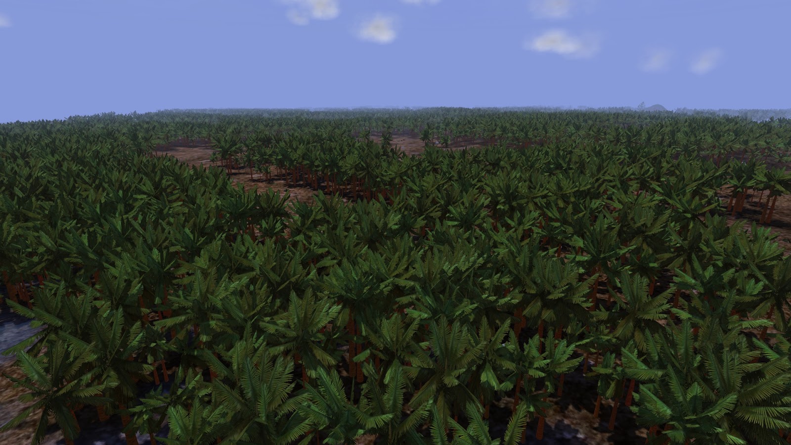
I recently optimized palm tree drawing using hardware instancing + Vertex Buffer Objects (VBOs) on the GPU. This allowed me to adjust the view distance of palm trees so that they're visible to the far fog distance, almost out to the horizon. Unlike pine trees, palm trees aren't usually rotationally symmetric about the Z (up) axis. I haven't been able to get billboards to work well with them. Therefore, each one is drawn in native polygon format using 20 palm fronds = 40 quads = 80 triangles each. In addition, trunks are drawn at various Levels of Detail (LODs) from single lines to 32-sided cylinders consisting of 32 quads = 64 triangles each. This allows me to draw more than 10K palm trees at over 100 FPS, as shown in the image below.

Tens of thousands of palm trees drawn out to the horizon at 143 FPS.

To finish off the screenshot gallery, I'll add an image of a sunset with long shadows and water reflections. If you look carefully, shadow maps are only used for nearby terrain tiles. You can tell which trees have shadows by looking at the lighting changes for distant trees. Terrain drawn beyond the shadow distance uses a more efficient, precomputed, low-resolution ambient occlusion lighting texture. These two modes are linearly blended to make a smooth transition for the player.

This is required to save GPU memory and CPU time for shadow map generation. I haven't used Cascaded Shadow Maps (CSMs) here because the overhead of drawing the scene multiple times (once per cascade) is too high, especially for the trees. Note that rendering tree billboards into the shadow map doesn't look correct; I have to use the full 3D polygon model of each tree, which is slow. There are a lot of polygons in all of those tree models! This is why I decided to precompute a separate static shadow map for each nearby tile instead.

Sunset on procedurally generated landscape and vegetation showing tree shadows and water reflections.

Finally, here is a video where I walk around the terrain and view some deciduous trees up close. You can watch me walk through a river similar to the one featured in the second image above. Then I enable flight mode and fly across the terrain at high speed. This demonstrates how quickly tiles can be generated as the player moves around in the world. In reality the framerate is a bit erratic, which can't actually be seen from a video played back at a fixed 60 FPS. The frame rate drops during frames where more than one tile needs to be generated, and the GPU must split its time between tile generation and scene rendering. In the end, I change the time of day. The sun goes down and the moon comes up, making interesting light reflections in the water.


This video shows that the grass blades are more than single triangles now when viewed from close up. This is a relatively new feature that was visible in some of my grass/tree fire screenshots but maybe not mentioned until now. I implemented this using tessellation shaders on the GPU. That's also how water waves are implemented in tiled terrain mode.

That's all for this post. Next time I'll probably talk about erosion simulation and water flow. I've experimented with these in the past but never mentioned them in the blog. I already have some interesting screenshots prepared. I haven't gotten erosion to work for infinite terrain tiles though. It currently only supports a single square tile at a time. I wonder if I'll be able to fix this in time for the next post.