This post continues my work on cube map reflections from where I left off in an earlier post on this topic. I had it working pretty well at the time. However, I was never able to get 100 reflective objects in the scene in realtime because I didn't have enough GPU memory on my 2GB card. I now have a GeForce GTX 1070 with 8GB of video memory, which should allow me to add as many as 300 reflective objects.
Another problem that I had with the earlier reflection framework was the lack of surface roughness support. Every object was a perfect mirror reflector. I did some experiments with mipmap biasing to try and get a proper rough surface (such as brushed metal), but I never got it working at a reasonable performance and quality point. I think I've finally solved this one, as I'll explain below.
3DWorld uses a Phong specular exponent (shininess factor) lighting model because of its simplicity. Physically based rendering incorporates more complex and accurate lighting models, which often include a factor for surface roughness. I'm converting shininess to surface roughness by mapping the specular exponent to a texture filter/mipmap level, which determines which power-of-two sampling window to use to compute each blurred output texel. I use an equation I found online for the conversion:
filter_level = log2(texture_size*sqrt(3)) - 0.5*log2(shininess + 1.0)
The problem with using lower mipmap levels to perform the down-sampling/blurring of the reflection texture is the poor quality of the filtering. Mipmaps use a recursive 2x2 pixel box filter, which produces blocky artifacts in the reflection as seen in the following screenshot. Here the filter_level is equal to 5, which means that each pixel is an average of 2^5 x 2^5 = 32*32 source texels. Click on the image to zoom in, and look closely at the reflection of the smiley in the closest sphere.
Rough reflection using mipmap level 5 (32x32 pixel box filter) with blocky artifacts.
The reflection would look much better with a higher order filter, such as a bi-cubic filter. Unfortunately, there is no GPU texture hardware support for higher order filtering. Only linear filtering is available. Adding bi-cubic texture filtering is possible through shaders, but is complex and would make the rendering time increase significantly.
An alternative approach is to do the filtering directly in the fragment shader when rendering the reflective surface, by performing many texture samples within a window. This is more of a brute force approach. Each sample is offset to access a square area around the target pixel. I use an NxN tap Gaussian weighted blur filter, where:
N = 2^(filter_level+1) - 1
A non-blurred perfect mirror reflection with filter_level=0 has a single sample computed as N = 2^(0+1)-1 = 1. [Technically, a single filter sample still linearly interpolates between 4 adjacent texels using the hardware interpolation unit.] A filter_level=5 Gaussian kernel has N= 2^(5+1)-1 = 63 samples in each dimension, for 3969 samples total. That's a lot of texture samples! It really kills performance, dropping the framerate from 220 FPS to only 19 FPS as shown in the screenshot below. Note the framerate in the lower left corner of the image. But the results look great!
Rough reflection using a 63x63 hardware texture filter kernel taking 3969 texture samples and running at only 19 FPS.
The takeaway is that mipmaps are fast but produce poor visual results, and shader texture filtering is slow but produces good visual results. So what do we do? I chose to combine the two approaches: select a middle mipmap level, and filter it using a small kernel. This has a fraction of the texture lookups/runtime cost, but produces results that are almost as high quality as the full filtering approach. For a filter_level of 5, I split this into a mipmap_filter_level of 2 and a shader_filter_level of 3. The mipmap filtering is applied first with a 2^2 x 2^2 = 4x4 pixel mipmap. Then the shader filtering is applied with a kernel size N= 2^(3+1)-1 = 15. The total number of texture samples is 15x15 = 225, which is nearly 18x fewer texture accesses. This gets the frame rate back up to around 220 FPS.
I'm not sure exactly why it's as fast as a 1x1 filter. The texture reads from the level 2 mipmap data are likely faster due to better GPU cache coherency between the threads. That would make sense if the filtering was texture memory bandwidth limited. I assume the frame rate is limited by something else for this scene + view, maybe by the CPU or other shader code.
Here is what the final image looks like. It's almost identical in quality to the 63x63 filter kernel image above. The amount of blur is slightly different due to the inexactness of the filter_level math (it's integer, not floating-point, so there are rounding issues). Other than that, the results are perfectly acceptable. Also, this image uses different blur values for the other spheres to the right, so concentrate on the closest sphere on the left for comparison with the previous two images.
Rough reflection using a combination of mipmap level 2 and a 15x15 texture filter kernel taking 225 texture samples.
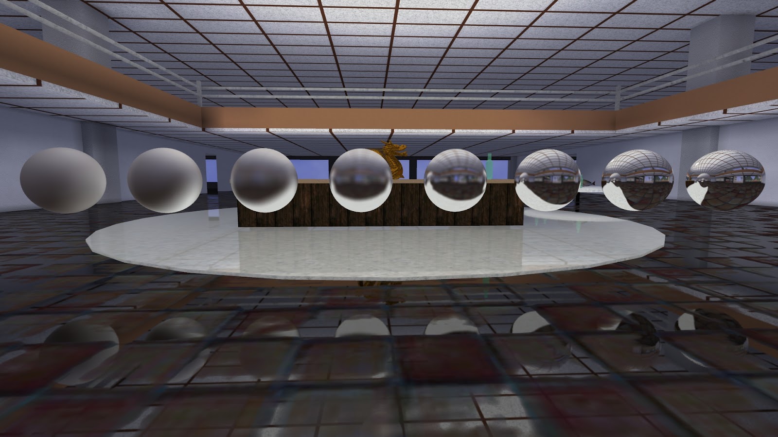
Here is a view of 8 metal spheres of varying roughness, from matte (fully diffuse lighting) on the left to mirror reflective (fully specular lighting) on the right. Each sphere is one filter_level different from the one next to it; the specular shininess factor increases by 2x from left to right.
Reflective metal spheres of varying roughness with roughest on the left and mirror smooth on the right.
This screenshot shows a closer view of the rough sphere on the left, with the filter_level/specular exponent biased a bit differently to get a clearer reflection. There are no significant filtering artifacts even at this extreme blurring level.
Smiley reflection in rough metal sphere showing high quality blur.
I'm pretty happy with these results, and the solution is relatively simple. The next step is to make the materials editable by the user and to make the reflective shapes dynamic so that they can be moved around the level. In fact, I've already done this, but I'll have to show it in a later post.
I recently installed a new version of Microsoft Visual Studio on my home machine where I develop 3DWorld. The upgrade from MSVS 2010 to MSVS 2015 had been delayed until I found a good deal on the latest version, which sells for hundreds of dollars. I managed to get a used copy on amazon.com for a fraction of the retail price, and it seems to work just fine.
Overall it only took me a few hours to get 3DWorld building and running with the new compiler. There were various minor fixes for syntax errors and warnings, and I had to rebuild some of the dependencies. However, the upgrade did require me to spend a lot of time setting up my universe mode scenes, for about the fourth time in the history of 3DWorld. My universe scenes were all invalidated and had to be reconstructed because the planets were different types and in different places. I had to re-place the ships and space stations and change various parameters.
The problem is that that the built-in random number generator values changed again. It seems like every version of Visual Studio gives me different values from rand(). Normally I wouldn't use the system rand() because it's slow, poor quality, and varies across compilers/OSes. I have my own custom random number generator that solves these three issues that I've been using since I switched to MSVS 2010 about 5 years ago. I thought that was the last time I would have to deal with the universe random seeds problem. I guess not.
Unfortunately, I missed a call to rand() that was used to precompute a table of Gaussian distribution random numbers to avoid generating Gaussian distributions on the fly. My custom random number generator was still being used to select a random entry from the Gaussian table, but the entries were all different. This distribution was used to select the temperature and radius of each system star. The star radius affected the planet orbits and the star temperature affected the planet types and environments. All of the galaxies and systems locations were the same, but within a solar system everything was different.
I fixed the problem and added a random seed config file parameter. This made it easy to regenerate the current system until I found one I liked, rather than having to fly around the galaxy looking for a suitable starting system for the player. I was looking for a seed that would give me a yellow to white star, an asteroid belt, and at least one of each type of interesting planet (Terran/Earth-like inhabitable, gas giant, ice planet, volcanic planet, ringed planet, etc.) In the process I came across some interesting and beautiful planets such as the gas giant in the screenshot below that looks like Jupiter.
Closeup of a procedural gas giant that looks like Jupiter, including small elliptical "storms".
Shadows
I settled on a system that had some interesting shadow effects, so I thought I would take some screenshots of the different types of objects that cast and receive shadows. Here is an image of a planet with a moon that is in the middle of the system's asteroid belt. I don't know if this actually happens in real solar systems, but it certainly makes for interesting gameplay. It's fun to watch the ships fly around the planet trying to (or failing to) avoid colliding with the asteroids. In this screenshot, I've positioned my ship so that the star is behind me and I'm in the shadow of the moon, looking at the asteroid belt and the planet, which is right in the middle of the asteroids.
Moon and planet casting shadows on an asteroid belt.
The small asteroids in the near field are fully shadowed and black, and the asteroids further away show a dark cone of shadow extending toward the planet in the center of the image. Some of the shadowed asteroids are difficult to see because they blend in with the black universe background, but you can definitely see shadowed asteroids contrasted against the planet. The shadow cone eventually disappears as the moon occludes a decreasing amount of the light from the star as the distance from the asteroid to the moon increases. This is similar to how, on Earth, shadows from nearby objects are much sharper than shadows from distant objects. Also note that the moon doesn't actually cast a shadow on the planet in its current position.
Here is a nice blue ocean planet that has a ring of asteroids around it. The ring casts a thin shadow near the equator of the planet. This can be seen as a thin dark line a bit below the center of the planet. This shadow is ray traced through the procedural ring density function in the fragment shader on the GPU to determine the amount of light that is blocked. The sun is behind my ship and a bit to the right. You can also see that the planet shadows the asteroid belt on the back left side. I found another planet where the moon should cast shadows on the rings, so I'll have to implement that in the code next.
Beautiful blue planet with asteroid belt rings. The rings cast a faint shadow on the planet and the planet casts a soft shadow on the rings.
I was lucky enough to find a rare occurrence of a moon casting a shadow on a planet - a solar eclipse! However, the relative sizes and distances between the star, moon, and planet in 3DWorld aren't to scale with real distances, so it may not represent a physically correct eclipse. I don't see these very often, and the previous planet configuration (MSVS 2010) didn't have one of these in any nearby star systems. The moon slowly revolves around the planet with an orbital period of around an hour, and after a few minutes of time the shadow no longer intersects the planet.
Rare occurrence of a moon casting a soft analytical shadow on a planet. The planet also reflects light onto the moon.
Note that the shadow has a physically correct umbra and penumbra. This is computed in the fragment shader when rendering the planet. The amount of light reaching the planet is calculated as one minus the fraction of the sun disk that is occluded by the moon. The sun is modeled as a circular/disk light source and the moon is modeled as a sphere projecting into a circle along the light vector. You can find the math for such a calculation here.
Bonus video of asteroid bowling! Here is a video of a planet plowing through the asteroid field at 100x speed, with a moon trailing behind it. I fixed the asteroid belt placement after recording this video.
Nebulae
Nebula rendering is not new to 3DWorld. I've shown images of 3DWorld's nebulae in previous posts such as this one. I recently went back and reworked the shader code that determines the color and transparency of each pixel in the nebula. I made a total of three changes:
Added an octave of low frequency 3D Perlin noise to modulate the density/transparency of the nebula to give it a more random, nonuniform shape rather than looking like a large sphere.
Increased the exponent of the noise from 2.0 to a per-nebula random value between 2.0 and 4.0 to produce stronger contrast between light and dark areas (wispy fingers).
Switched to additive blending to model emissive gas rather than colored occluding material for high noise exponent nebulae to give them a brighter appearance.
Here are some nebula screenshots. They show the evolution of nebula rendering as I applied my changes to the algorithm. The first two show the original algorithm, the middle two show changes 1 and 2, and the last four images show the final code. The stars in these screenshots are in front of, inside, and behind the nebula.
Keep in mind that nebulae are volumetric objects computed using 3D noise, not just 2D images. They are drawn with 13 crossed billboards, allowing the player to fly in and around them with minimal rendering artifacts. I got the idea from this video.
That's it for nebulae. I'll add some more images if I change the algorithm again in the future. Sorry, I haven't created any nebula videos. The fine color gradients just look horrible after video compression, and it ruins the wispy, transparent effect.
This is a followup post to my indirect lighting post of last year. I decided that I wanted moving objects such as doors to also influence indirect lighting in the scene. This is more difficult than handling light sources that can be switched on and off by the player. Moving objects have more than on/open and off/closed states - they have all the intermediate positions representing partially open states. Storing only two states isn't enough, and linearly interpolating between them doesn't work well for all cases. The light moves with the object. Consider a moving object that starts entirely to the left side of an opening through which light can pass, then moves entirely to the right. At both extremes it blocks no light, but at the midpoint of its path it blocks the entire opening, resulting in a dark room. This condition can't be achieved by interpolating between the end points, which would both be at the same lighting solution (fully lit).
These types of moving objects are called platforms in 3DWorld. They're named after the platforms used for doors and elevators in the Forge map editor for Marathon, a game I played in college long ago. 3DWorld platforms can move in any direction, and can be used for doors, elevators, crushers, machines, etc. Custom triggers can be attached to platforms to control them. These triggers can be activated by the player, or can be proximity sensors triggered by the player or smiley AIs. The example door shown in the images and video below are activated by four player controlled switches placed on the walls by the door. I even made the switches an emissive yellow color so that they can easily be seen in the dark.
Back to lighting. I briefly considered storing precomputed lighting values for several intermediate points along the platform's motion. There are some problems with this approach. One issue is that a small number of precomputed points doesn't provide a very accurate interpolation across the lighting values as the platform moves. A large number of points takes too much CPU time to compute and too much disk space to store. Also, the number of blocks of saved lighting data increases exponentially as multiple interacting platforms are added. For example, if the scene contains two adjacent doors A and B, they may interact with each other. Door A might block most of the light reaching door B. If they're both in series along the same hallway, light won't reach the end of the hallway unless both doors are open. This is difficult to automatically detect just by looking at the geometry of the doors and the hallway. We instead need to store a minimum of four lighting states: {A and B closed, A and B open, A open B closed, A closed B open}. If there are three doors, we need 8 states. It quickly gets out of control as the data scales exponentially with the number of doors/platforms.
This problem is similar to the one discussed at the end of this blog post for the game "The Witness". I remember reading about the exponential combination problem on their blog somewhere, but I can't seem to find it now. However, their indirect lighting system is entirely different from the one used in 3DWorld, so the trade-offs are also somewhat different.
My second idea was to cache the rays intersecting any possible position of each platform, and sort out which rays are blocked at runtime, based on the current door position(s). The platform is expanded to cover the union of it's possible positions by extending it in a line between it's start and end points. This proxy object is added to the bounding volume hierarchy prior to ray tracing. Then, when computing indirect lighting, any ray that could hit the platform in any of its possible positions will hit this proxy geometry. All rays intersecting the proxy are terminated (no longer propagate) and stored in a file on disk. This process is only done once, after which the file is loaded and its data reused. At the end, the proxy is removed and replaced with the actual platform in its initial position. All saved rays are re-cast, and any rays not intersecting the platform position add reflected indirect light to the scene. This additional light "L" represents the initial/nominal lighting of the scene, and is saved to the precomputed indirect lighting file for future use.
When the platform moves, the rays need to be re-evaluated to determine which ones are blocked by the platform in its updated position. The simplest approach is to remove the contribution of "L" from the scene and recompute it using the new platform position. While this works, and is simple, it's not a very good solution. Every ray would need to be re-cast every frame the platform is moving. This kills the frame rate, and makes the game unplayable. Clearly, an incremental approach is needed.
The key observation is that the platform moves slowly relative to each game frame and lighting changes incrementally. A door doesn't open or close in a single frame. If it takes one second to move across its path, and the game is running at 60 FPS (Frames Per Second), we can spread the lighting update across all 60 frames to get a nice smooth framerate. The trick is to determine which rays change state from blocked to unblocked between the previous and current frames. This can be done by testing each saved ray against the platform's bounding volume, which is very easy to parallelize across multiple threads. In most cases, the vast majority of rays are either blocked or unblocked in both frames. Only a small fraction of rays will change state, and only these rays need to be re-cast to update the lighting values.
[Note that I'm ignoring rays that intersect the platform at different points in the previous and current frames, even though the reflected lighting will change. In practice the error introduced by this is insignificant compared to the magnitude of the transmitted rays, especially if the platform is a dark, non-reflective color. I'm also ignoring rays that reflect off the same platform multiple times, as again their contribution to the full lighting solution should be negligible. Light rays lose their energy quickly when reflecting off multiple diffuse objects.]
Rays that were previously blocked but become unblocked this frame can be transmitted through the scene, and recursively reflected off other objects as they are in the precomputed ray tracing phase. If the same random seeds are used as in the precomputation phase, the rays will be exactly the same, and the lighting will look as if these rays were never blocked in the first place. Any rays that newly become blocked have their weights/colors negated so that they remove light from the scene during ray tracing. The platform is temporarily removed from the bounding volume hierarchy, and ray tracing proceeds as usual with the negative rays. This will cancel out the light that was added when these rays were included in the lighting solution earlier. When the platform moves back to its original position, everything happens in reverse, where all rays have weights negated from what they were in the forward motion of the platform. Therefore, the lighting solution will converge to the original/nominal value once the platform comes to rest. In reality there is a small amount of floating-point error, and maybe some non-determinism from using multiple threads without locking or atomic operations. But, after dozens of door open/close cycles, I can't see any visual difference in the lighting.
Okay, that's enough text. How about some images? I don't really have anything too exciting to show this time. Here is a screenshot of the basement, with the basement door open. The only light source is the sky and indirect sunlight coming in through the door. Sorry the image is so dark. The door is very small compared to the enormous room, so it doesn't get very bright in here. At least it's realistic lighting for such a room.
Basement with door open, letting the outside indirect light in.
And here is the same viewpoint with the basement door closed.
Basement with door closed, blocking most of the outside indirect light. A small amount of light is leaking from the door.
The basement should be completely black, except for the tiny emissive yellow door switches. The small amount of leaked light on the right side of the door is due to the way the 3D light volume texture is sampled in the fragment shader. Lighting is linearly interpolated across voxels (3D texture pixels), which produces a smooth transition from light to dark along thin objects such as the door. Since the walls are at least one light voxel in width, they properly block all of the light.
Here is a view from the outside looking into the basement, with the door in the process of closing. The basement is partially lit in this case, where the right side of the basement is slightly brighter than the left side because the door is open on the right.
Closeup of the basement door half-way closed, seen from the outside looking in.
It's easier to see the smooth transition in a video. Lighting is updated incrementally each frame the door is moving. As long as the door moves slowly enough, only a small number of rays need to be recomputed per frame. Lighting updates have a minimal impact on frame rate. This particular door has a total of 96K intersecting light rays and moves over the course of 1.6 seconds, taking an average of only 1.3ms of realtime with 8 threads across 4 CPU cores (0.9ms for ray tracing and 0.4ms for GPU texture update).
I'll hopefully add some more dynamic lighting platforms later, once I get the system properly tuned. This same solution should be general enough that it works for a wide variety of platforms.
The next step is to make this system work with fixed position static light sources such as room lights. It would be interesting to see a closet light that can be turned on and off, so that when the closet door is open and the light is on it indirectly lights the adjacent room. After that, I could try to make this work with dynamic point light sources, such as explosion effects. Of course, I haven't even gotten the regular static indirect lighting working in this case, so it could take significant effort.
I added asteroid belts to 3DWorld a while back, maybe a year or so ago. I thought they looked pretty good at the time. Recently I watched an asteroid belt video from the Kickstarter campaign of the Infinity: Battlescape space game. Sorry, I can't seem to find the original video, but here is a similar video by the same team/company. I realized that my asteroid belts lacked the fine reflective particle clouds that add a sense of volume to the scene. I decided to reuse the same procedural volumetric fog/cloud framework that was used for nebulae, explosions, and clouds in 3DWorld.
That wasn't my first approach. I originally wanted to ray cast into the asteroid belt volume and perform ray marching through it, integrating a randomly generated density field along the way. This is similar to how volumetric fog was done in 3DWorld as shown in this previous post. This technique works well when your scene is a large cube, but unfortunately isn't so easy when the domain is a complex shape such as a circular asteroid belt.
Asteroid Belt Bounding Volume
Let me take a step back and explain how asteroid belts are created in 3DWorld, in particular how their shape and asteroid distribution is chosen. There are two types of 3DWorld asteroid belts: system asteroid belts and planetary ring asteroid belts. 3DWorld also has spherical asteroid fields, but those work differently and won't be discussed here. System asteroid belts orbit the star in a solar system, similar to the orbits of planets. Planetary asteroid belts surround a single planet and are much smaller in size (radius) and asteroid count.
Each asteroid belt is generated by placing asteroids in a Gaussian distribution around an elliptical path in the orbital plane of the system or planet. The entire set of asteroids is contained within a non-uniformly scaled torus volume. The orbital plane normal forms the z (center) axis of the torus, like an axle through a tire. The z-scale is typically set to around 25% of the x/y scales to produce a flattened shape that resembles a thin disk. The x and y scales can be different, producing a non-circular (ellipsoid) shape. There is also an inner radius and outer radius for the torus.
This is not a very nice shape to work with, since it is mathematically fairly complex and involves higher order trigonometric functions. It's much easier to perform a series of transforms to convert the asteroid belt shape into a unit (normalized) torus using the following steps:
Translate the torus by the asteroid belt center to put the origin at (0,0,0)
Rotate the torus so that its axis is oriented in the +z direction
Scale the torus independently in x, y, and z to produce a circular shape with an inner radius of 1
It's fairly easy to determine if a point is inside of the asteroid belt volume by applying these transforms and checking for point-in-torus. Sphere intersection is more complex, but not too bad. However, computing the intersection points of a line with a torus is much more difficult because it requires solving for the roots of a quartic equation. There are up to four intersection points. I managed to find some existing source code to do this, but it's not something I would have wanted to derive, write, and debug myself. If you must know, parts of the source code can be found here and here. If you're really interested in the math, here is a fun paper that's guaranteed to keep you busy for a while or put you to sleep. If anyone knows of a simpler way to compute the intersection of a line with a torus, please let me know. Bonus points if it works both on the CPU and on the GPU.
Anyway, if you remember from the second paragraph, the volume ray marching approach requires computing all intersection points of a line with the asteroid belt bounding volume on the GPU. This would require porting the transform code, quartic solver code, and torus intersection code to GLSL. Now, I'm sure this would be possible, but it would be a huge time sink to debug, and there may be floating-point precision issues if it was all done on the shader in single precision. And it would probably be very slow. I decided to abandon that approach and go with something different and (hopefully) easier.
Asteroid Placement
Let me explain how asteroids are actually placed and rendered to produce a realistic volume consisting of millions of asteroids of various sizes. There are three types of asteroids drawn:
Large asteroids drawn as procedurally generated 3D triangle meshes; Up to 10,000 instances of 100 uniquely generated asteroids; They dynamically move and rotate over time.
Smaller asteroid point sprites that are rendered as spheres in the fragment shader; 1M generated, though only nearby asteroids are visible
Smaller asteroids drawn as points to fill in the gaps when the player is near or within the belt; ~100K points per few degree arc slice of visible nearby torus (~1M max visible)
This set of asteroids fill in the space in the belt fairly well. Type 1 asteroids are highly detailed and also include normal mapping and procedural craters to make them look more convincing. The smaller points and spheres are thrown in as part of the background to trick the user into thinking there are millions of large, detailed asteroids out there. It works!
Asteroid Belt Screenshots
Here is a screenshot of what these three types of asteroids look like together. This is just a small section of the asteroid belt, maybe 1-2% of the total. How many asteroids does it look like this section contains?
Closeup view of an asteroid in the asteroid belt showing normal mapped craters and a nebula in the background.
Pretty good, but the density is not as high as the asteroids in the original Infinity video. Something needs to be added to fill the spaces between the meshes, spheres, and points. How about some procedural, reflective dust clouds?
Asteroid belt with procedural volumetric dust clouds reflecting the star's light, shaded with the star's color.
This looks much better. The asteroid belt has more volume and looks more interesting. The dust clouds properly occlude asteroids that lie behind them and produce a sort of fog in the distance. The dust is a yellowish color based on the star's color. Now it looks like there really are millions of asteroids visible, from huge ones to tiny bits of dust. Of course it's another trick, there are only a few thousand of them. Here is another view of this system asteroid belt, from outside looking in toward the star.
Asteroid belt and reflective dust clouds viewed from the outside facing the yellow star.
Note that the dust clouds extend further outside the torus envelope than the asteroids themselves. This seems to make sense physically: Larger, heavier asteroids are affected more by gravity, making them revolve around the star or planet faster, and forcing them into a thinner ring in the orbital plane. At least it may be correct to first order.
Here is an example of a cold, icy planetary asteroid belt, viewed from slightly above.
Cold planet with surrounding asteroid belt containing ice crystals and reflective dust.
The clouds seem to gently rise up out of the orbital plane with very slow animated motion. The star is
behind and below the camera, causing the asteroid belt to cast
ring-shaped shadows on the top part of the planet.
Here is a video of my ship flying into the system asteroid belt, bouncing off two large asteroids (collision detection is enabled), then flying to a ringed planet and crossing through its asteroid belt.
Rendering - How It's Done
There are 100 unique dust cloud models generated when the first asteroid belt becomes visible, and they're shared across multiple belts. The vertex data is stored in GPU memory for fast access for drawing. Limiting the number of unique clouds cuts down on CPU time and GPU memory. Each large type 1 asteroid has a dust cloud instance attached to it with a small random translational offset to make cloud placement look more random. Clouds are attached to asteroids so that they move with them, without having to independently compute orbital vectors for yet another type of object on the CPU. This way, there is no explicit physics update for dust clouds. They need to move to track a planet that revolves around the star. The movement also adds more dynamic effects to the rendering, which makes it more interesting. As a bonus, cloud positions don't need to be generated within the asteroid belt bounding torus as they inherit that property (approximately) from the asteroids they're attached to. This makes the code much simpler.
Each cloud model consists of 9 intersecting quad billboards that cover an approximately equally spaced set of normal vectors on the unit sphere. This is fewer than the 13 billboards used for nebulae and explosions, for a different quality vs. performance trade-off. The various billboards are faded in and out by modifying their transparency (alpha) values based on view distance and view angle. Distant clouds are faded to transparent and skipped to improve rendering time, since they don't contribute much to the final image. Clouds very close to the player/camera are also faded out to reduce the amount of fragment shader overdraw and minimize worst case framerate.
The GPU fragment shader computes per-pixel transparency by evaluating 4 octaves of 3D Perlin noise, where each octave is implemented as a lookup into a 3D precomputed noise texture. I used 4 octaves rather than the 5 octaves used for nebulae and explosions to improve performance. Since 9 billboards are used, a few of them are oriented toward the camera for every possible camera position, producing an illusion of a 3D volume with simulated parallax. Asteroid clouds have the most impact on performance when the camera is in the middle of the belt and the fragment shader must do significant work computing noise values. On average, enabling clouds reduces the framerate of this case from 260FPS to 140FPS, which is reasonable.
I chose a fairly simple lighting model for asteroid belt clouds. I assume the clouds are composed of small particles that reflect the star's light in all directions like tiny, randomly oriented mirrors. No explicit light scattering is modeled (yet). I also assume that the occlusion of the particles themselves is negligible, so that unlit/shadowed particles are effectively invisible. This is similar to how dust that is normally invisible will shine when it's caught in a path of sunlight in a room. With this approach, the lighting is independent of the camera view direction and the star's light direction, which simplifies the math and makes the shader faster. The CPU can simply intersect each dust cloud's light ray with the nearby planets and moons to determine which are in shadow. Shadowed clouds are simply not drawn, since they contribute no light and are assumed to produce no significant occlusion. The end result is that non-shadowed clouds are lit using the star's color and an intensity based on the distance to the star with a quadratic falloff.
Partially transparent surfaces are typically drawn in back-to-front depth order so that alpha blending works properly. However, sorting thousands of clouds by depth on the CPU is an expensive process. The sort would need to be performed every frame as both the camera and the clouds are moving. I decided to omit this sort, since it works well enough without it. Each cloud is around 95% transparent, so the depth sorting errors are barely noticeable, especially with alpha testing enabled.
Update: I added the sort, after filtering by distance and view frustum culling. It only seems to add around 1% additional render time. It makes very little difference in the final image, so it's probably not necessary. For reference, the culling, sorting, and the rest of the CPU side of rendering only takes around 0.3ms.
Planets
This post so far has been a wall of text, but not too many fancy pictures/videos. Here are some bonus screenshots of planets showing off planetary clouds and other effects.
View from moon orbit showing a highly detailed moon surface with normal maps and GPU tessellation, a Terran planet behind it, and an asteroid belt in the distance.
This first image shows a closeup of a moon's surface. The high resolution
procedural normal map is generated from height differences in the
fragment shader. The moon's horizon is also very detailed thanks to the
tessellation shader that converts a low polygon sphere into a detailed,
bumpy planet. A procedural Terran planet and some large procedural voxel asteroids are visible in the background. [The asteroids are probably unreasonably large.] Behind them are the system asteroid belt, and behind that is an ice and rock planet. You can even see a few space ships floating around by the moon and near planet.
Water/ocean planet and moon. The planet is covered with clouds that cast shadows on the water.
This image shows a cloudy ocean planet in a solar system with a yellow-orange sun. The clouds are procedurally animated in the fragment shader and cast shadows on the water under them. A moon is shown to the left, with a volumetric nebula behind it. This nebula uses a rendering approach similar to the asteroid belt clouds, but it uses three color channels rather than an alpha channel only. In addition, the nebula uses ridged noise and different noise constants.
I'm still working on the trees in 3DWorld's tiled terrain mode. I made another pass at optimizations which increased the frame rate by 10%-20%. I also made improvements to the tree placement algorithm, giving the trees a more natural and less artificial look. Here are some of the latest screenshots of the terrain from the air, with all types of trees, vegetation, and scenery, with all effects enabled.
Island trees viewed from above. Note that trees are self-shadowing.
View from above the pine trees, looking out across the terrain at the other tree types in the foggy distance.
Tree types are selected based on elevation. Pine trees are placed at the highest elevation, palm trees are placed at low elevations near water, and deciduous trees are placed in intermediate areas. Grass and flowers are also placed at low to mid elevation, with grass density based on the sky/sun visibility from each point on the ground. Visibility is determined from precomputed mesh and tree occlusion maps stored in each terrain tile.
Palm trees are new to tiled terrain mode. I added some experimental palm trees to some of the other scenes a few months ago, including the office building scene which appeared in earlier blog posts. I had to rewrite the palm tree rendering to be more efficient by storing the tree vertex data on the GPU instead of the CPU. This allowed the placement of over a thousand visible palm trees in the scene with minimal additional frame time.
Palm trees are drawn using the same shaders and a similar rendering path to pine trees. However, I still don't have a good low-detail distant model for palm trees. Billboards work well for pine trees since they're mostly rotationally symmetric, but they don't work well for palm trees. There is too much popping and too many rendering artifacts on palm tree leaves when transitioning from a geometry model to a billboard image model. This will be future work.
Deep in the forest, among the trees. A (new!) bush has been placed to the lower left of the center of the image.
Deciduous trees are generated from five different species, where a
set of random noise weight maps is used to select the species of each
tree. The species that has the highest weight is selected for placement at each chosen location.
This produces clumps of trees of the same type, similar to what appears in a real forest. The original placement
was too regular though, so I added another layer of random noise to blur
the boundary between the tree types. Now there are some sparsely places
trees of a different species mixed into the clumps of trees of one species.
This looks much more natural, and makes an amazing difference for such a
small change to the tree placement algorithm.
3DWorld procedurally generates 10 variants of
each tree species, giving a
total of 50 unique trees to be instanced in the scene. In addition, some bushes are generated by changing the tree parameters to remove the trunk and translate the tree down into the ground. The number of unique trees is mostly limited
by GPU memory usage (on my old computer), and can be made higher for less detailed trees.
This appears to be enough unique trees that it's nearly impossible to
spot two duplicates next to each other. My new computer has 2 GB of graphics memory, so I could increase the number to 100 unique trees, but it seems unnecessary.
View of the bay with grass and palm trees.
More palm trees by the bay, with birds in the sky, reflective water, and distant fog.
I also improved the elevation-based tree placement to remove the
hard lines between pine/deciduous/palm trees that caused the transition
between tree type to exactly follow elevation contours. This looked
very unnatural. The solution was to use the low bits of the
floating-point number representing tree height to adjust the placement parameters. These low bits are
deterministic but random enough that the pattern isn't noticeable. The
random bits are multiplied by a large constant and added to the
elevation value, producing a more randomized tree type contour that
allows multiple types to be mixed near the elevation boundary. Now there
are five different elevation regions: palm, palm+deciduous, deciduous,
deciduous+pine, and pine. You can see pine + deciduous tree types mixed together in the first screenshot at the top of the page, and palm + deciduous trees mixed in the screenshot below.
Grassy, sandy beach with distant mountains.
Lighting, shadows, and fog work on all tree and plant types. Everything casts and receives shadows. Ambient occlusion is calculated and combined with shadows to create darker areas under dense tree coverage. The image below shows darker shadowed areas in the front and right, contrasted to a bright open area in the back left. Note that grass density is higher in bright areas.
A tree covered, shadowy hillside.
Here is a video of me walking (or running?) around on the ground, from a medium elevation point on the mountain side down to the water, and along the beach. Everything you see is procedurally generated with no load time and rendered in realtime at around 60 FPS. If this video looks too small or blurry, you can try the direct link to my video on YouTube here. I'll have to see if I can find a video hosting site that allows me to post longer videos that have less compression artifacts, so that you can see more details - for example, how all of the leaves move in the wind.
Note that, unlike most other forest videos I've seen online, there are almost no visual artifacts or "popping" of trees or terrain. There are a few places in the video (mostly near the end) where some "dissolve" level-of-detail transitions are present, but they are distant and minor. This was difficult to achieve with thousands of visible trees containing up to 20 thousand individual leaf polygons.
Can you spot any duplicate instanced trees? It's unlikely. There are 50 unique deciduous tree models, and each pine tree, palm tree, and plant is uniquely generated.
I haven't done too much new in 3DWorld over the past month. I've mostly been working on performance optimizations for tree rendering and bug fixes for ship combat in universe mode. Maybe at some point I'll make a post on one of those topics, but I don't have enough interesting content for either of them yet.
Last week, I read Alexandre Pestana's post on Volumetric Lights. This got me thinking about adding this effect to 3DWorld. In fact, I had already added this a while back, but I never posted any of the screenshots. It took a bit of effort to get it working again, and now I can write a blog post about it.
I've already talked about rendering "God rays", a type of volumetric lighting, in a previous blog post. Here is a screenshot from a few months ago, where the sun rays are visible through the leaves of a palm tree.
"God Rays" showing through palm trees using a screen space postprocessing pass.
This is a nice, fast screen-space technique, but it only works when the light (sun in this case) is visible. And it only works for uniform fog density. I needed a better system without these limitations, even if it meant spending more frame time drawing the fog. I decided to add this feature to my smoke effects shader code path, but have the fog density come from a procedural function rather than a 3D smoke texture constructed from smoke diffusion on the CPU.
I used a standard volumetric ray marching technique to step from the scene hit point to the viewer in eye space using uniform steps. This integration process calculates the lighting and fog effects for every pixel in the fragment shader on the GPU. The operations performed at each step are as follows:
Sample the indirect area lighting term from a 3D texture to get the ambient color at this point.
Check the shadow map 2D texture at this point to see if there is direct lighting from the sun.
Evaluate a 3D noise function to determine the smoke/fog density at this location.
Combine all of the terms to compute the change in color at this step using the equations:
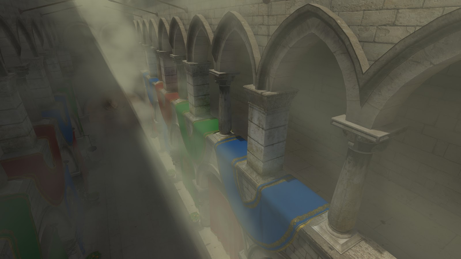
The color starts out as the lit scene pixel color. If there was no fog (fog_density=0), this is the color returned. Higher fog density will replace more of the original color with the lit fog color at each step. This method accounts for light scattering to a first order approximation with exponential falloff. It works well and produces some nice results, but is very slow. Here are some screenshots showing fog in the Crytek Sponza Atrium scene.
Dense volumetric fog with shadows in the Crytek Sponza Atrium scene.
Sponza Atrium with fog, half of it in light and the other half in shadow.
Here I'm using a 128x128x256 indirect lighting texture, a single 4096x4096 shadow map texture, and a screen resolution of 1920x1080 (1080p). I'm taking 3 samples per lighting pixel, which can be more than 200 samples per pixel but is on average much smaller. I get around 20FPS with all effects enabled. The framerate increases to 40-50 FPS at 1280x720 (720p), which is more reasonable for a realtime game. Most of the time is taken by steps 1 and 2. If I reduce the number of steps/samples, the framerate improves significantly, but the quality degrades and some rendering artifacts start to appear. If I reduce the indirect lighting or shadow map texture resolution, the framerate will also improve, at the cost of more noise and less lighting precision. Blocky lighting doesn't look very good.
Here is another screenshot that shows how important the indirect lighting term is. The fog near the fire on the right glows with an orange hue. If I remove the indirect term, the fog will be black, which looks very wrong. The fog on the left side is brighter due to indirect lighting from the sun in the open courtyard. You can also see the shafts of light in the back center of the image where the sun shines through the space above the curtains.
Volumetric fog with direct sunlight + shadows, and indirect lighting from the fire on the right.
The previous images all used a constant fog density. 3DWorld can also use procedural 3D Perlin noise to generate time-varying, nonuniform fog density. This looks more like smoke that slowly drifts across the scene. I used 3 noise octaves, which seemed to be a good balance between runtime and quality. The additional three 3D texture lookups add significant overhead to the fog computation time, and reduce the framerate by about 20%. But, it does look much nicer. Here are some screenshots.
GPU-generated volumetric smoke that moves/flows dynamically and is light by both indirect and direct light with shadows.
Dynamic volumetric smoke, lit by a shaft of sunlight, viewed from above.
Volumetric smoke with shadows and light shafts.
Finally, here is a video showing how the smoke moves over time. The camera is motionless; only the smoke is moving.
3DWorld also has a smoke diffusion model that can be used in gameplay mode. Some of the weapons produce smoke, and others create fire, which also produces smoke. The smoke is diffused though a 3D volume with collision model blockers on the CPU. Then the volume data is sent to the GPU for use in rendering. I may make a blog post on this topic later.
I would like to use this effect for some game content, but it's not clear if the performance/quality trade-off curve has any useful points. It's either too slow, or the quality is not good enough. Still, it's a nice demo effect, and fine for small screen resolutions. I'll have to look into some possible optimizations. I've read that randomly distributing the same points reduces the rendering artifacts but produces noise. Maybe the results would be more acceptable? In some cases a screen-space blur can remove most of the noise, but it's not clear if the 3DWorld framework can do this blur correctly in its current form. Maybe I'll experiment with this later.
I just got back from my trip to Spain, and it's time to write another blog post. I guess I'm done working on reflections in 3DWorld for now, so I've moved on to other features. You won't see as many fancy screenshots in this post.
I've wanted to make infinite tiled terrain mode more interesting for a long time. I have first person shooter gameplay in ground mode, but that's just a small map area. Tiled terrain mode is a much larger area (infinite!), which makes it more difficult to place interesting items and to fight enemies in. I needed something to make it feel more alive, even if it's not really part of gameplay.
My first thought was to have animals jump out of the water, grass, and trees at the player, maybe make it some sort of hunting game - either the animals hunt the player, or the player hunts the animals. I decided to start with some simple animals that should be easy to create: fish in the water, and birds in the sky. The general idea is that they don't have to be highly detailed models since they won't be viewed from up close. Fish can swim away when the player gets too close. Birds are high in the sky where the player can't get to unless flying mode is enabled. This means that I can concentrate on the AI behavior (which is fun) rather than create detailed models (which is slow and tedious, and requires software that I don't have installed).
The general theme of tiled terrain mode is that all tiles are self-contained cubes laid out in a uniform sized X-Y grid that extends 10-12 units in all directions around the camera/player. Tiles extend in Z from the lowest point in the ocean to somewhere above the clouds. As the player moves, new tiles are created when they come into view distance range, and old tiles are deleted when they're far enough away. Everything is contained in the tiles: terrain, water, trees, grass, rocks, clouds, etc. It makes sense that animals should also belong to tiles. This allows animals to be created or "spawned" when new tiles come into view, and distant animals can be deleted when tiles fall out of the view area, so that the number of active animals is roughly constant.
The problem is, animals aren't static like the rest of the scene. They move. When an animal crosses its containing tile's boundary, it's removed from one tile and added to another tile. This complicates things, and means that my custom, high precision coordinate system doesn't work correctly for animals. An animal's location can't be relative to a tile's local coordinate system if it doesn't belong to a single tile. I haven't quite solved this issue. I suspect that when the player walks far enough away from the origin, the animals will begin to have jittery movements as floating-point error accumulates. However, I haven't actually noticed this problem, maybe because the fish and birds are far enough away. So for now I'll ignore the issue.
Fish
Fish and birds are generated within each tile. I decided on a max of 12 fish per tile and 2 birds per tile. For each tile, 12 fish xy locations are generated, and the mesh height is calculated for each position. If the mesh point is under the water, the fish is kept. A z-value (depth) is randomly chosen for that fish between the mesh z-value and the water surface z-value. The fish can move in the xy plane but stays at this constant depth/z to simplify the collision detection and AI logic. Fish swim in a straight line and occasionally make small adjustments to their directions. If they collide with the mesh, they choose a new direction to move in. If they get too close to the player, they turn around and swim away. This produces a natural looking behavior.
Fish need to perform collision detection with the mesh under the water surface each frame when they move. For procedurally generated simplex noise meshes, that requires evaluating the noise function one or more times per-fish per-frame. With 400 generated tiles, and 12 fish per tile, that's 4800 updates per frame corresponding to 6000-8000 height evaluations of 8 octaves of simplex noise per frame, which takes many CPU cycles. Normally, the noise is evaluated in parallel on the GPU. This doesn't work for the scattered, random position evaluations of fish. Evaluating it on the CPU has a noticeable impact on frame rate, which was reduced from 300 FPS to 130 FPS. I decided that there was no reason to move fish that were miles away from the player and not even visible. Reducing the simulation distance to some 100 feet reduced the number of "active" fish to 10-20 and completely solved the problem.
I originally thought that fish would be easy to simulate and draw. I could have them swim away when the player got close, preventing them from being viewed close-up. That way, they could be drawn as simple untextured ellipsoids (non-uniformly scaled spheres) that faded into the water color at a distance. Later, I realized that it was possible to corner fish in shallow water so that they couldn't swim away from the player, allowing the player to get very close to them. The ellipsoid shape just didn't work. In the end, I had to find a textured 3D fish model on TurboSquid and figure out how to integrate that into the world. This is the first time I had to add support for dynamic imported 3D models with arbitrary translation, rotation, and scale transforms. They still blend into the background water color with distance, to simulate a fog effect for murky water.
In the end, the fish models worked well. They weren't animated models, so the tails and fins were static, but that didn't seem to matter too much. Here is a screenshot of some fish under the water, taken with the camera positioned in the air above the water. Normally, the fish will swim away at this distance, but I temporarily disabled the fish AI to prevent them from moving.
Fish viewed from above the water surface.
Here is a screenshot of fish viewed from underwater.
Fish viewed from underwater.
Birds
I originally thought it would be difficult to make birds look natural and real, but birds were actually easier than fish to draw. They're viewed from a distance, so their model didn't need much complexity. I was able to get away with making birds plain black, formed from three ellipsoids representing their body and two wings. The wings of each bird are animated using a simple sine wave for up/down motion. They fly with a constant velocity in the xy plane, with an altitude/z-value randomly between the top of the highest mountain and the bottom layer of puffy clouds. Birds move in slowly varying random directions that form wide curved paths, keeping them from quickly flying out of view. These wide curving paths seem to make believable flight paths.
Birds cross through tiles relatively quickly, since they move at higher speeds than fish (and the player). The birds that cross the final edge tiles that have no generated neighbors are gone forever. I suppose if you stay in one place watching the birds for a long time, eventually they'll all fly away. However, it seems like when I look at them for minutes their numbers aren't even reduced noticeably, so it may take closer to an hour for most of them to fly away.
The birds fly above the highest peaks, so no collision detection is necessary. It might be more realistic to have them take off from and land on trees (if trees are even enabled), but that seems much more difficult. I haven't implemented collision detection with the tree crowns/leaves yet, only the trunks.
Here are two screenshots of birds flying in the sky. Note that they can fly in and out of clouds. Since clouds are volumetric, the birds alpha blend with them correctly. This likely doesn't happen in nature, except for some of the high flying species of birds (or very low clouds).
Birds flying in the sky, controlled by steering AI.
Birds in the sky, flying in and out of the clouds.
Here is a video showing birds flapping their wings and flying through the sky. Somehow YouTube didn't ruin this one with compression artifacts - I wonder what I did differently this time?
I'm thinking of adding bees and butterflies next. These would be similar to birds, except that the player can get closer to them so they need to have a more detailed drawing model. Also, they will need to do some sort of collision detection with trees and flowers. 3DWorld already has basic collision detection for some of the scenery, though it would be slow for a large number of insects.
Maybe I can also add spiders that fall out of the trees when the player walks under them. They can come down on webs and then walk around on the ground. I'm not sure how difficult it would be to animate a spider's legs, but it sure would be scary!