In theory, 3DWorld should be rendering these materials using close to physically correct lighting models. Of course, there could be bugs. I have no idea how to check for correctness. Some of the materials I can create may not exist in the real world, such as a half metal half glass. Or a material that absorbs/scatters blue light and reflects red light. Maybe they exist, but I don't have any around for reference, and good luck finding a reference image for something like that online.
What's changed since I last blogged about this stuff? I think I finally have refraction working correctly with per-object cube maps, at least for cubes and spheres. These two shapes are simple enough that I can ray trace them inside the shader to compute correct ray intersection points and reflection/refraction angles. The shader code is pretty complex as it handles up to two reflections and two refractions corresponding to both the front and back faces of transparent materials. In addition, it handles volumetric light scattering and light absorption/attenuation. This is what we see in volumetric/solid, partially transparent materials such as ice, glass blocks, colored plastic, liquids such as milk, etc.
There are an incredibly large combination of material parameters that I can create in 3DWorld, so I can't possibly show them all in this post. At best I can show a dozen or so examples. Here is the set of parameters that can be edited in realtime that affect lighting (excluding parameters used for physics):
Texture, Emission, Reflectivity, Metalness, Alpha, Specular Magnitude, Shininess, Refraction Index, Light Attenuation, Diffuse Red, Diffuse Green, Diffuse Blue, Specular Red, Specular Green, and Specular Blue. These user parameters are explained more in my previous blog post on this topic.
Parameters are changed through my simple onscreen editing system where the arrow keys select the variables and move the sliders. It's similar to a monitor's onscreen menu system. Maybe it's not the best or nicest looking UI, but it's simple to use, easy to work with in the code, and has almost no impact on framerate. Plus, it avoids having to pull in a 3rd party UI library and figure out how to make it work in fullscreen mode when 3DWorld only supports a single window + render target. I did, however, add a texture preview image and some small color indicator circles. Everything but the texture image is ASCII art. If I ever release 3DWorld to the public, I'll have to add a better UI.
Here is an example of a refractive glass cube and sphere together. Refraction currently only works correctly with sphere and cube shapes; other shapes are approximated without knowing the exit point of the view ray from the object. You can see the reflection of the sphere in two of the back faces of the cube. The fragment shader traces each view ray through the object. The ray is both reflected and refracted at the front surface of the shape (the current pixel's 3D position in the fragment shader). The refracted ray is then intersected with the back face of the shape using a ray-sphere or ray-cube intersection. The hit position is reflected back into the shape, and also refracted out of the shape into air. The reflection and refraction angles depend on the indexes of refraction at the material/air interface. Each of the rays that exits the shape is looked up in the correct face of the reflection cube map to determine the color to use for blending. This produces first-order physically correct reflections and refractions, as seen in the image below.
 |
| Glass cube and sphere drawn using a cube map with two reflections and two refractions, in shadow. |
Does that look like a real glass cube? Maybe. I do have a clear plastic cube that I used as a reference last year. Unfortunately, I seem to have misplaced it after moving to the new house. The sphere certainly looks like images of glass spheres I found on Google (example). It has the typical inverted, zoomed out refraction image of glass spheres. However, I don't have the physical parameters (such as index of refraction) for the glass used in those images, so I can't do an accurate comparison. A small change in index of refraction makes a large change in the reflections and refractions, especially the second order ones. The difference is amplified with each reflection/refraction.
I've also experimented with more than two reflections/refractions, but this didn't seem to improve the results, so I left it out. It definitely changed the results, but it wasn't clear that they were more correct. I don't think the average human can detect correct third order reflection/refraction effects. Also, multiple bounces in spheres tends to magnify part of the image, which makes the pixel borders of the cube map texture more obvious. I would rather have a smooth and clean image than one that is every so slightly more physically correct. Besides, this adds extra complexity and reduces framerate.
Here are some screenshots where I was experimenting with different diffuse and specular colors. The blueish diffuse and reddish specular makes these glass objects look like anti-reflective coated lenses as used in cameras and some sunglasses.
 |
| Textured glass "marble" with reflection, refraction, and scattering using custom material texture and colors. The smiley face is my placeholder player model! |
 |
| The glass eyeball. |
Normal maps can be applied to object as well to perturb the reflection/refraction normal vector and get some interesting effects.
 |
| Glass ... pumpkin? Well, this is a wooden fence normal map applied to a sphere. |
I made some attempts at creating ice. I don't have any ice normal maps, so I had to make do with the normal maps I happen to have. The stucco normal map shown in the first video at the bottom looks like a natural chunk of ice. These two cubes look more like ice sculptures or something else man made.
 |
| Ice cube? More like ice bricks. |
 |
| Another ice cube, using a different normal map texture. Since it's supposedly transparent, it doesn't cast a shadow. |
Light absorption and scattering within the material volume is also supported. This is sometimes referred to as participating media. The way this works is by calculating the length of the view ray clipped to the bounds of the sphere or cube for each fragment in the shader. This is the distance light must travel to cross the 3D volume of the object. The amount of light absorption/scattering varies exponentially as exp(distance) and is used to blend between the cube map ray hit color and the material's bulk color.
I can add hundreds of cubes and spheres and they're all drawn in depth sorted order for correct alpha blending. You can see the reflections and refractions between all of the objects. Is this physically correct? I have no idea, it's not obviously wrong as far as I can tell. I've seen similar effects in image searches such as this one. The exact value for index of refraction makes a huge difference.
 |
| Refractive glass cubes and spheres that absorb and scatter light. They also reflect and refract each other. |
Here is a screenshot of the San Miguel scene from the previous blog posts, this time with some interesting glass and metal objects on the ground. The gold sphere can be seen twice in the glass sphere. On the left is a refraction, and on the right is a reflection off the inside surface of the sphere. It looks like it could be physically correct. If I only had a glass sphere and gold sphere I could probably figure it out. Is anyone interested in donating these to me in the name of science?
 |
| Material spheres placed in the San Miguel scene. The reflective gold sphere is reflected and refracted in the glass sphere. |
I created two videos showing material editing. Both videos were recorded in realtime. As long as a single sphere or cube is placed or moved at one time, the framerate remains high. There is a list of predefined materials read from a text file. The UI allows for editing of existing materials to create new named materials. These can be saved in the scene for later use. Dynamic objects can have their parameters modified after placement if their named material is the one being edited. This is because they store a reference back to their material. However, the cube map is rendered every frame, so this only works well for a single dynamic object. Multiple objects reduce framerate due to all the required scene rendering passes. Static objects, on the other hand, can be placed all over the scene until graphics memory is exhausted (a few hundred objects on my system). The downside is that their material parameters can't be modified once they're placed. Both types of objects can be moved by the player and also destroyed.
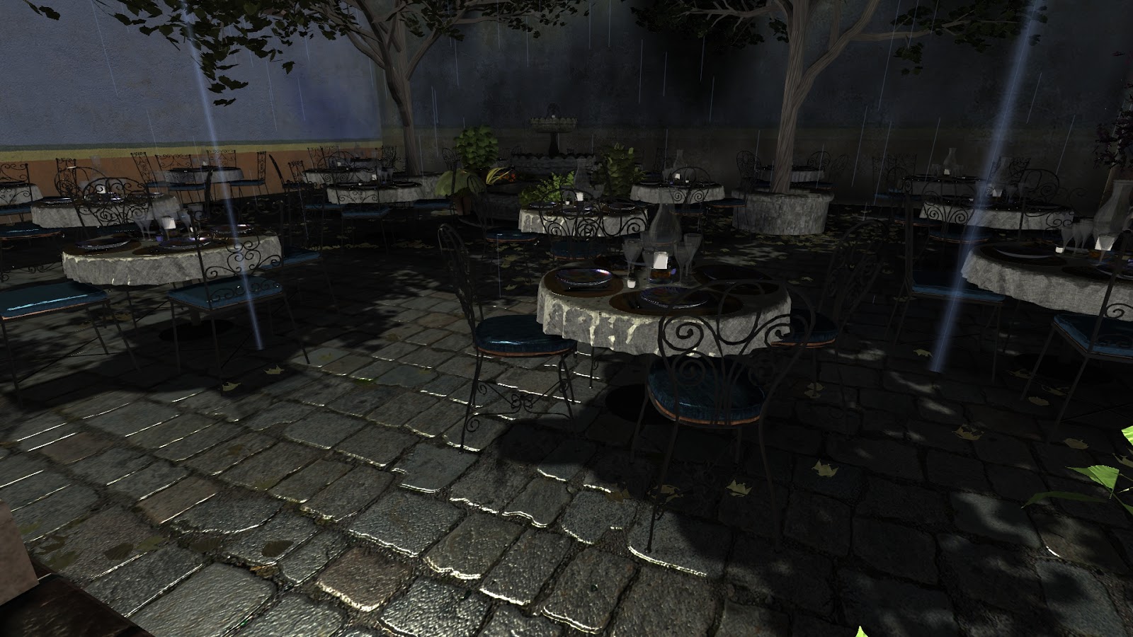
Here is a similar video, this time in the San Miguel scene shown in the previous two blog posts. The only collision object is the ground. The tables and chairs weren't added as collision objects because they're not really grouped in a convenient way in the model file, and I haven't computed their bounding volumes. 3DWorld really prefers volumetric collision objects rather than polygon-based ones. I could add all ~7M polygons as individual collision objects, and it would probably work, but the performance would be terrible. I'm not sure if 3DWorld could actually fit the data + acceleration structure in 32-bit address space. So you can ignore the fact that I'm pushing cubes through tables and chairs, because I haven't bothered to fix it. Also note that the final cube's refraction image looks a bit odd because it's partially sticking though the wall.
That's all I have for now. I have a lot more images and videos of more materials with strange parameters, but I feel I've shown enough of the interesting ones.
The question is, what can I do with these? Is it possible to build an entire building or game level with them? I guess I need to add support for shapes other than cubes and spheres. Technically, I do have other shapes, but I hard-coded the parameters into the source code rather than adding a proper UI for controlling them. I've already created a scene with over 10K cubes so I know it scales, as long as they're not all reflective and refractive. 10K opaque/diffuse objects and 100 reflective/refractive objects should be fine for a realtime scene. Of course, it would be an incredible amount of work to build something useful from them if every object needs to be individually placed. I suppose I can continue to use these objects as decorations. And yes, they can be saved and reloaded, keeping most of the parameters. I can no longer edit object materials properties after reloading.